Wing flaps are a movable part of the wing, normally hinged to the inboard trailing edge of each wing. Flaps are extended or retracted by the pilot. Extending the flaps increases the wing camber, wing area (some types), and the angle of attack of the wing. This increases wing lift and also increases induced drag. The increased lift enables the pilot to make steeper approaches to a landing without an increase in airspeed. Their use at recommended settings also provides increased lift under certain takeoff conditions. When the flaps are no longer needed, they can be retracted.
Pilots are cautioned to operate the flaps within the airspeed limitations set forth for the particular airplane being flown. If the speed limitations are exceeded, the increased drag forces created by extending the flaps could result in structural damage to the airplane.
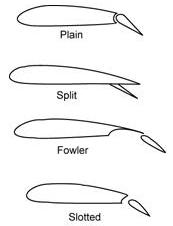
| Figure 2-1 shows the four types of flaps in general use. The plain or simple flap is a portion of the trailing edge of the wing on a hinged pivot which allows the flap to be moved downward, thereby changing the chord line, angle of attack, and the camber of the wing. The split flap is a hinged portion of the bottom surface of the wing only, which when extended increases the angle of attack by changing the chord line. The Fowler flap, when extended, not only tilts downward but also slides rearward on tracks. This increases angle of attack, wing camber, and wing area, thereby providing added lift without significantly increasing drag. The slotted flap in addition to changing the wing’s camber and chord line also lets a portion of high pressure air beneath the wing travel through a slot. This increases the velocity of air and increases lift. |
 |
|
|
Landing Gear
The landing gear system supports the airplane during the takeoff
run, landing, taxiing, and when parked. These ground operations require
that the landing gear be capable of steering, braking, and absorbing shock.
A steerable nose gear or tailwheel permits the airplane to be
controlled by the pilot throughout all operations while on the ground.
Individual brakes installed on each main wheel permit the pilot to use
either brake individually as an aid to steering or, by applying both brakes
simultaneously, the pilot can decelerate or stop the airplane. Hydraulic
shock struts or leaf springs are installed in the various types of landing
gear systems to absorb the impact of landings, or the shock of taxiing
over rough ground.
There are two basic types of landing gear used on light airplanes.
These are:
• Conventional Landing Gear
• Tricycle Landing Gear
Conventional Landing Gear
The conventional landing gear, which was used on most airplanes manufactured years ago, is still used on some airplanes designed for operations on rough fields. This landing gear system consists of two main wheels and a tailwheel. Shock absorption is usually provided on the main landing gear by inflated tires and shock absorbers while it is provided on the tailwheel by a spring assembly to which the tailwheel is bolted. The tailwheel is usually steerable by the rudder pedals through at least 15° on each side of a center point beyond which it becomes full swiveling.
Tricycle Landing Gear
The tricycle landing gear is used on most airplanes produced today. This gear has advantages over the conventional gear because it provides easier ground handling characteristics. The main landing gear is constructed similar to the main landing gear on the conventional system, but is located further rearward on the airplane. The nose gear is usually steerable by the rudder pedals.
Some airplanes are equipped with a retractable landing gear. Retracting the gear reduces the drag, and increases the airspeed without additional power.
The landing gear normally retracts into the wing or fuselage through an opening which is covered by doors after the gear is retracted. This provides for the unrestricted flow of air across the opening which houses the gear. The retraction or extension of the landing gear is accomplished either electrically or hydraulically by landing gear controls from within the cockpit. Indicators are provided in the cockpit to indicate whether the wheels are extended and locked, or retracted. In retractable landing gear installations, a system is provided for emergency gear extension in the event the normal landing gear mechanism fails to lower the gear.