3-4
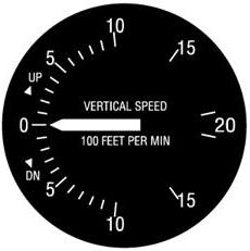
| Vertical Speed Indicator
The vertical speed indicator (VSI) or vertical velocity indicator
indicates whether the aircraft is climbing, descending, or in level flight.
The rate of climb or descent is indicated in feet per minute. If properly
calibrated, this indicator will register zero in level flight. [Figure
3-3]
|
|
|
Figure 3-3.—Vertical speed indicator.
|
Principle of Operation
Although the vertical speed indicator operates solely from static
pressure, it is a differential pressure instrument. The case of the instrument
is airtight except for a small connection through a restricted passage
to the static line of the pitot-static system.
A diaphragm with connecting linkage and gearing to the indicator
pointer is located inside the sealed case. Both the diaphragm and the case
receive air from the static line at existing atmospheric pressure. When
the aircraft is on the ground or in level flight, the pressures inside
the diaphragm and the instrument case remain the same and the pointer is
at the zero indication. When the aircraft climbs or descends, the pressure
inside the diaphragm changes immediately; but due to the metering action
of the restricted passage, the case pressure will remain higher or lower
for a short time causing the diaphragm to contract or expand. This causes
a differential pressure which is indicated on the instrument needle as
a climb or descent.
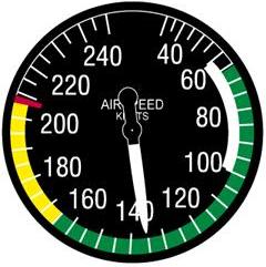
| Airspeed Indicator
The airspeed indicator is a sensitive, differential pressure gauge
which measures and shows promptly the difference between (1) pitot, or
impact pressure, and (2) static pressure, the undisturbed atmospheric pressure
at level flight. These two pressures will be equal when the aircraft is
parked on the ground in calm air. When the aircraft moves through the air,
the pressure on the pitot line becomes greater than the pressure in the
static lines. This difference in pressure is registered by the airspeed
pointer on the face of the instrument, which is calibrated in miles per
hour (MPH), knots, or both. [Figure 3-4]
Kinds of Airspeed
There are three kinds of airspeed that the pilot should understand:
• Indicated Airspeed
• Calibrated Airspeed
• True Airspeed |
|
|
Figure 3-4.—Airspeed indicator.
|
Indicated Airspeed
Indicated airspeed (IAS) is the direct instrument reading obtained
from the airspeed indicator, uncorrected for variations in atmospheric
density, installation error, or instrument error.
Calibrated Airspeed
Calibrated airspeed (CAS) is indicated airspeed corrected for
installation error and instrument error. Although manufacturers attempt
to keep airspeed errors to a minimum, it is not possible to eliminate all
errors throughout the airspeed operating range. At certain airspeeds and
with certain flap settings, the installation and instrument error may be
several miles per hour. This error is generally greatest at low airspeeds.
In the cruising and higher airspeed ranges, indicated airspeed and calibrated
airspeed are approximately the same.
It may be important to refer to the airspeed calibration chart
to correct for possible airspeed errors because airspeed limitations such
as those found on the color-coded face of the airspeed indicator, on placards
in the cockpit, or in the Airplane Flight Manual or Owner’s Handbook are
usually calibrated airspeeds. Some manufacturers use indicated rather than
calibrated airspeed to denote the airspeed limitations mentioned.
The airspeed indicator should be calibrated periodically because
leaks may develop or moisture may collect in the tubing. Dirt, dust, ice,
or snow collecting at the mouth of the tube may obstruct air passage and
prevent correct indications, and also vibrations may destroy the sensitivity
of the diaphragm.
True Airspeed
The true airspeed indicator (TAS) is calibrated to indicate true
airspeed under standard sea level conditions—that is, 29.92 in. Hg. and
15° C. Because air density decreases with an increase in altitude,
the airplane has to be flown faster at higher altitudes to cause the same
pressure difference between pitot impact pressure and static pressure.
Therefore, for a given true airspeed, indicated airspeed decreases as altitude
increases or for a given indicated airspeed, true airspeed increases with
an increase in altitude.
A pilot can find true airspeed by two methods. The first method,
which is more accurate, involves using a computer. In this method, the
calibrated airspeed is corrected for temperature and pressure variation
by using the airspeed correction scale on the computer.
A second method, which is a “rule of thumb,” can be used to compute
the approximate true airspeed. This is done by adding to the indicated
airspeed 2 percent of the indicated airspeed for each 1,000 feet of altitude.
Airspeed Indicator Markings
Airplanes weighing 12,500 pounds or less, manufactured after 1945
and certificated by the FAA, are required to have airspeed indicators that
conform in a standard color-coded marking system. This system of color-coded
markings enables the pilot to determine at a glance certain airspeed limitations
which are important to the safe operation of the aircraft. For example,
if during the execution of a maneuver, the pilot notes that the airspeed
needle is in the yellow arc and is rapidly approaching the red line, immediate
corrective action to reduce the airspeed should be taken. It is essential
at high airspeed that the pilot use smooth control pressures to avoid severe
stresses upon the aircraft structure. [Figure 3-4]
The following is a description of the standard color-code markings
on airspeed indicators used on single-engine light airplanes:
• FLAP OPERATING RANGE (the white arc).
• POWER-OFF STALLING SPEED WITH THE WING FLAPS AND LANDING GEAR IN THE
LANDING POSITION (the lower limit of the white arc).
• MAXIMUM FLAPS EXTENDED SPEED (the upper limit of the white arc). This
is the highest airspeed at which the pilot should extend full flaps. If
flaps are operated at higher airspeeds, severe strain or structural failure
could result.
• NORMAL OPERATING RANGE (the green arc).
• POWER-OFF STALLING SPEED WITH THE WING FLAPS AND LANDING GEAR RETRACTED
(the lower limit of the green arc).
• MAXIMUM STRUCTURAL CRUISING SPEED (the upper limit of the green arc).
This is the maximum speed for normal operation.
• CAUTION RANGE (the yellow arc). The pilot should avoid this area unless
in smooth air.
• NEVER-EXCEED SPEED (the red line). This is the maximum speed at which
the airplane can be operated in smooth air.
This speed should never be exceeded intentionally.
Other Airspeed Limitations
There are other important airspeed limitations not marked on the
face of the airspeed indicator. These speeds are generally found on placards
in view of the pilot and in the Airplane Flight Manual or Pilot’s Operating
Handbook.
One example is the MANEUVERING SPEED. This is the “rough air”
speed and the maximum speed for abrupt maneuvers. If during flight, rough
air or severe turbulence is encountered, the airspeed should be reduced
to maneuvering speed or less to minimize the stress on the airplane structure.
Other important airspeeds include LANDING GEAR OPERATING SPEED,
the maximum speed for extending or retracting the landing gear if using
aircraft equipped with retractable landing gear; the BEST ANGLE-OF-CLIMB
SPEED, important when a short-field takeoff to clear an obstacle is required;
and the BEST RATE-OF-CLIMB SPEED, the airspeed that will give the pilot
the most altitude in a given period of time. The pilot who flies the increasingly
popular light twin-engine aircraft must know the aircraft’s MINIMUM CONTROL
SPEED, the minimum flight speed at which the aircraft is satisfactorily
controllable when an engine is suddenly made inoperative with the remaining
engine at takeoff power. The last two airspeeds are now marked either on
the face of the airspeed indicator or on the instrument panel of recently
manufactured airplanes.
Descriptions of these airspeed limitations are, through choice,
limited to layman’s language.
The following are abbreviations for performance speeds:
VA—design maneuvering speed.
VC—design cruising speed.
VF—design flap speed.
VFE—maximum flap extended speed.
VLE—maximum landing gear extended speed.
VLO—maximum landing gear operating speed.
VLOF—lift-off speed.
VNE—never-exceed speed.
VR—rotation speed.
VS—the stalling speed or the minimum steady flight speed at which the
airplane is controllable.
VS0—the stalling speed or the minimum steady flight speed in the landing
configuration.
VS1—the stalling speed or the minimum steady flight speed obtained
in a specified configuration.
VX—speed for best angle of climb.
VY—speed for best rate of climb.