Several flight instruments utilize the properties of a gyroscope for their operation. The most common instruments containing gyroscopes are the turn coordinator, heading indicator, and the attitude indicator. To understand how these instruments operate requires a knowledge of the instrument power systems, gyroscopic principles, and the operating principles of each instrument.
Sources of Power for Gyroscopic Operation
In some airplanes, all the gyros are vacuum, pressure, or electrically operated; in others, vacuum, or pressure systems provide the power for the heading and attitude indicators, while the electrical system provides the power for the turn coordinator.
Vacuum or Pressure System
The vacuum or pressure system spins the gyro by drawing a stream of air against the rotor vanes to spin the rotor at high speeds essentially the same as a water wheel or turbine operates. The amount of vacuum or pressure required for instrument operation varies with manufacture and is usually between 4.5 to 5.5 in. Hg.
Engine-Driven Vacuum Pump
One source of vacuum for the gyros installed in light aircraft is the
vane-type engine-driven pump which is mounted on the accessory case of
the engine. Pump capacity varies in different aircraft, depending on the
number of gyros to be operated.
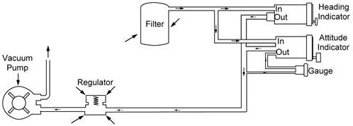
A typical vacuum system consists of an engine-driven vacuum pump,
regulator, air filter, gauge, tubing, and manifolds necessary to complete
the connections. The gauge is mounted in the airplane instrument panel
and indicates the amount of pressure in the system. [Figure 3-5]
The air filter prevents foreign matter from entering the vacuum or pressure system. Airflow is reduced as the master filter becomes dirty; this results in a lower reading on the vacuum or pressure gauge.
Gyroscopic Principles
Any spinning object exhibits gyroscopic properties; however, a wheel designed and mounted to utilize these properties is called a gyroscope. Two important design characteristics of an instrument gyro are great weight or high density for size and rotation at high speeds with low friction bearings. The mountings of the gyro wheels are called “gimbals” which may be circular rings, rectangular frames, or a part of the instrument case itself.
There are two general types of mountings; the type used depends upon which property of the gyro is utilized. A freely or universally mounted gyroscope is free to rotate in any direction about its center of gravity. Such a wheel is said to have three planes of freedom. The wheel or rotor is free to rotate in any plane in relation to the base and is so balanced that with the gyro wheel at rest, it will remain in the position in which it is placed. Restricted or semirigidly mounted gyroscopes are those mounted so that one of the planes of freedom is held fixed in relation to the base.
There are two fundamental properties of gyroscopic action;
rigidity in space, and precession.
|
Rigidity in space can best be explained by applying Newton’s First Law of Motion which states, “a body at rest will remain at rest; or if in motion in a straight line, it will continue in a straight line unless acted upon by an outside force.” An example of this law is the rotor of a universally mounted gyro. |
| Figure 3-5.—Typical pump-driven vacuum system. |
The flight instruments using the gyroscopic property of rigidity for their operation are the attitude indicator and the heading indicator; therefore, their rotors must be freely or universally mounted.
| The second property of a gyroscope—precession—is the resultant action or deflection of a spinning wheel when a deflective force is applied to its rim. When a deflective force is applied to the rim of a rotating wheel, the resultant force is 90° ahead in the direction of rotation and in the direction of the applied force. The rate at which the wheel precesses is inversely proportional to the speed of the rotor and proportional to the deflective force. The force with which the wheel precesses is the same as the deflective force applied (minus the friction in the bearings). If too great a deflective force is applied for the amount of rigidity in the wheel, the wheel precesses and topples over at the same time. [Figure 3-6] |
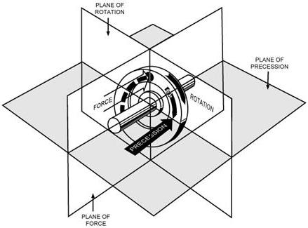 |
| Figure 3-6.—Precession of a gyroscope resulting from an applied deflective force. |
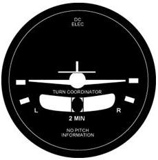 |
Turn Coordinator The turn coordinator shows the yaw and roll of the aircraft around the
vertical and longitudinal axes.
|
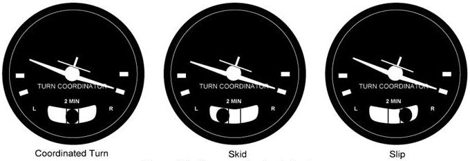
Figure 3-8.—Turn coordinator indications.
 |
The Heading Indicator
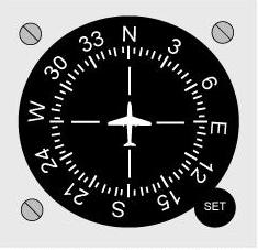 |
The heading indicator (or directional gyro) is fundamentally a mechanical
instrument designed to facilitate the use of the magnetic compass. Errors
in the magnetic compass are numerous, making straight flight and precision
turns to headings difficult to accomplish, particularly in turbulent air.
A heading indicator, however, is not affected by the forces that make the
magnetic compass difficult to interpret. [Figure 3-9]
The operation of the heading indicator depends upon the principle of rigidity in space. The rotor turns in a vertical plane, and fixed to the rotor is a compass card. Since the rotor remains rigid in space, the points on the card hold the same position in space relative to the vertical plane. As the instrument case and the airplane revolve around the vertical axis, the card provides clear and accurate heading information. |
|
|
Bear in mind that the heading indicator is not direction-seeking, as is the magnetic compass. It is important to check the indications frequently and reset the heading indicator to align it with the magnetic compass when required. Adjusting the heading indicator to the magnetic compass heading should be done only when the airplane is in wings-level unaccelerated flight; otherwise erroneous magnetic compass readings may be obtained.
The bank and pitch limits of the heading indicator vary with the particular design and make of instrument. On some heading indicators found in light airplanes, the limits are approximately 55° of pitch and 55° of bank. When either of these attitude limits is exceeded, the instrument “tumbles” or “spills” and no longer gives the correct indication until reset. After spilling, it may be reset with the caging knob. Many of the modern instruments used are designed in such a manner that they will not tumble.
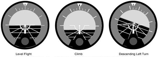
The Attitude Indicator
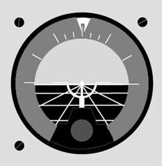 |
The attitude indicator, with its miniature aircraft and horizon bar,
displays a picture of the attitude of the airplane. The relationship of
the miniature aircraft to the horizon bar is the same as the relationship
of the real aircraft to the actual horizon. The instrument gives an instantaneous
indication of even the smallest changes in attitude. [Figure 3-10]
The gyro in the attitude indicator is mounted on a horizontal plane and depends upon rigidity in space for its operation. The horizon bar represents the true horizon. This bar is fixed to the gyro and remains in a horizontal plane as the airplane is pitched or banked about its lateral or longitudinal axis, indicating the attitude of the airplane relative to the true horizon. |
|
|
 |
|
|