![]()
|
|
||
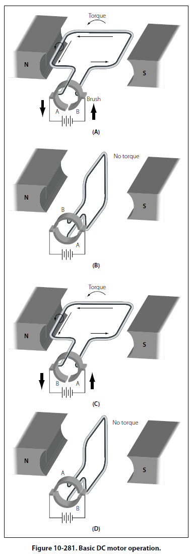
Basic DC Motor A coil of wire through which the current flows will rotate when placed in a magnetic field. This is the technical basis governing the construction of a DC motor. Figure 10-281 shows a coil mounted in a magnetic field in which it can rotate. However, if the connecting wires from the battery were permanently fastened to the terminals of the coil and there was a flow of current, the coil would rotate only until it lined itself up with the magnetic field. Then, it would stop, because the torque at that point would be zero.
A motor, of course, must continue rotating. It is therefore necessary to design a device that will reverse the current in the coil just at the time the coil becomes parallel to the lines of force. This will create torque again and cause the coil to rotate. If the current reversing device is set up to reverse the current each time the coil is about to stop, the coil can be made to continue rotating as long as desired. One method of doing this is to connect the circuit so that, as the coil rotates, each contact slides off the terminal to which it connects and slides onto the terminal of opposite polarity. In other words, the coil contacts switch terminals continuously as the coil rotates, preserving the torque and keeping the coil rotating. In Figure 10-281, the coil terminal segments are labeled A and B. As the coil rotates, the segments slide onto and past the fixed terminals or brushes. With this arrangement, the direction of current in the side of the coil next to the north-seeking pole flows toward the reader, and the force acting on that side of the coil turns it downward. The part of the motor, which changes the current from one wire to another, is called the commutator. |
| ©AvStop Online Magazine Contact Us Return To Books |