![]()
|
|
||
Resonance It has been shown that both inductive reactance (XL = 2 ∏f L) and capacitive reactance: XC = 1/2 ∏ f C …are functions of an alternating current frequency. Decreasing the frequency decreases the ohmic value of the inductive reactance, but a decrease in frequency increases the capacitive reactance. At some particular frequency, known as the resonant frequency, the reactive effects of a capacitor and an inductor will be equal. Since these effects are the opposite of one another, they will cancel, leaving only the ohmic value of the resistance to oppose current flow in a circuit. If the value of resistance is small or consists only of the resistance in the conductors, the value of current flow can become very high. In a circuit where the inductor and capacitor are in series, and the frequency is the resonant frequency, or frequency of resonance, the circuit is said to be “in resonance" and is referred to as a series resonant circuit. The symbol for resonant frequency is Fn. If, at the frequency of resonance, the inductive reactance is equal to the capacitive reactance, then:
Where Fn is the resonant frequency in cycles per second, C is the capacitance in farads, and L is the inductance in henries. With this formula, the frequency at which a capacitor and inductor will be resonant can be determined. To find the inductive reactance of a circuit use: XL = 2 (∏) f l
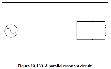
Since at the resonant frequency XL cancels XC, the current can become very large, depending on the amount of resistance. In such cases, the voltage drop across the inductor or capacitor will often be higher than the applied voltage. In a parallel resonant circuit, the reactances are equal and equal currents will flow through the coil and the capacitor. [Figure 10-133]
Since the inductive reactance causes the current through the coil to lag the voltage by 90°, and the capacitive reactance causes the current through the capacitor to lead the voltage by 90°, the two currents are 180° out of phase. The canceling effect of such currents would mean that no current would flow from the generator and the parallel combination of the inductor, and the capacitor would appear as infinite impedance. In practice, no such circuit is possible, since some value of resistance is always present, and the parallel circuit, sometimes called a tank circuit, acts as very high impedance. It is also called an antiresonant circuit, since its effect in a circuit is opposite to that of a series resonant circuit, in which the impedance is very low. |
| ©AvStop Online Magazine Contact Us Return To Books |

.jpg)
).jpg)