
![]()
|
|
||
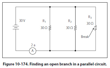
Tracing Shorts with the Ohmmeter The shorted resistor shown in Figure 10-172 can be located with an ohmmeter. First the switch is opened to isolate the circuit components. In Figure 10-172, this circuit is shown with an ohmmeter connected across each of the resistors. Only the ohmmeter connected across the shorted resistor shows a zero reading, indicating that this resistor is shorted. Tracing Shorts with the Voltmeter To locate the shorted resistor while the circuit is functioning, a voltmeter can be used. Figure 10-173 illustrates that when a voltmeter is connected across any of the resistors, which are not shorted, a portion of the applied voltage will be indicated on the voltmeter scale. When it is connected across the shorted resistor, the voltmeter will read zero. Troubleshooting the Open Faults in Parallel Circuit The procedures used in troubleshooting a parallel circuit are sometimes different from those used in a series circuit. Unlike a series circuit, a parallel circuit has more than one path in which current flows. A voltmeter cannot be used, since, when it is placed across an open resistor, it will read the voltage drop in a parallel branch. But an ammeter or the modified use of an ohmmeter can be employed to detect an open branch in a parallel circuit. If the open resistor shown in Figure 10-174 was not visually apparent, the circuit might appear to be functioning properly, because current would continue to flow in the other two branches of the circuit.
To determine that the circuit is not operating properly, a determination must be made as to how the circuit should behave when working properly. First, the total resistance, total current, and the branch currents of the circuit should be calculated as if there were no open in the circuit. In this case, the total resistance can be simply determined by:
Because the other two branches are of the same resistive value, then the current in each of those branches will be 1 ampere also. Adding up the amperes in each branch confirms the initial calculation of total current being 3 amperes. |
| ©AvStop Online Magazine Contact Us Return To Books |

.jpg)