POWERED FLIGHT
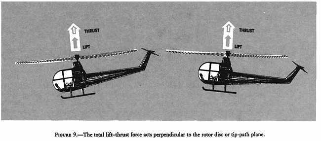
In any kind of flight (hovering, vertical, forward, sideward, or rearward), the total lift and thrust forces of a rotor are perpendicular to the tip-path plane or plane of rotation of the rotor (fig. 9). The tip-path plane is the imaginary circular plane outlined by the rotor blade tips in making a cycle of rotation.
Figure 9 - The total lift-thrust force acts perpendicular to the rotor disc or tip-path plane.
Forces acting on the helicopter
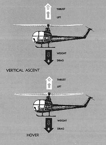
During any kind of horizontal or vertical flight, there are four forces acting on the helicopter - lift, thrust, weight, and drag. Lift is the force required to support the weight of the helicopter. Thrust is the force required to overcome the drag on the fuselage and other helicopter components.
Hovering flight - During hovering flight in a no-wind condition, the tip-path plane is horizontal, that is, parallel to the ground. Lift and thrust act straight up; weight and drag act straight down. The sum of the lift and thrust forces must equal the sum of the weight and drag forces in order for the helicopter to hover.
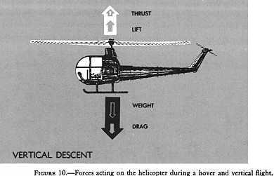
Vertical flight - During vertical flight in a no wind condition, the lift and thrust forces both act vertically upward. Weight and drag both act vertically downward. When lift and thrust equal weight and drag, the helicopter hovers; if lift and thrust are less than weight and drag, the helicopter descends vertically; if lift and thrust are greater than weight and drag, the helicopter rises vertically (fig. 10).
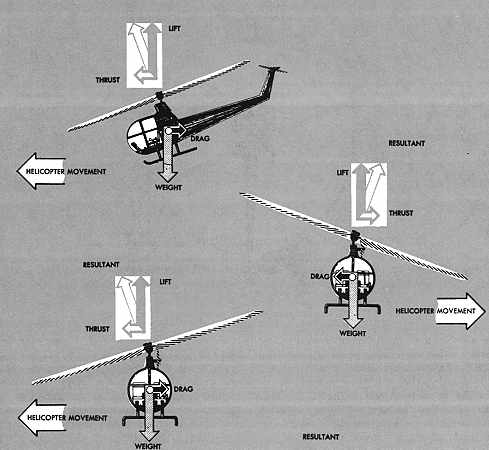
Forward flight - For forward flight, the tip-path plane is tilted forward, thus tilting the total lift-thrust force forward from the vertical. This resultant lift-thrust force can be resolved into two components - lift acting vertically upward and thrust acting horizontally in the direction of flight. In addition to lift and thrust, there are weight, the downward acting force, and drag, the rearward acting or retarding force of inertia and wind resistance (fig. 11).
In straight-and-level unaccelerated forward flight, lift equals weight and thrust equals drag (straight-and-level flight is flight with a constant heading and at a constant altitude). If lift exceeds weight, the helicopter climbs; if the lift is less than weight, the helicopter descends. If thrust exceeds drag, the helicopter speeds up; if thrust is less than drag, it slows down.
Sideward flight - In sideward flight, the tip-path plane is tilted sideward in the direction that flight is desired thus tilting the total lift-thrust vector sideward. In this case, the vertical or lift component is still straight up, weight straight down, but the horizontal or thrust component now acts sideward with drag acting to the opposite side (fig. 11).
Figure 10 - Forces acting on the helicopter during
a hover and vertical flight.
|
|
Rearward flight - For rearward flight, the tip-path plane is tilted rearward tilting the lift-thrust vector rearward. The thrust component is rearward and drag forward, just the opposite to forward flight. The lift component is straight up and weight straight down (fig. 11).
Figure 11 - Forces acting on the helicopter during
forward, sideward, and rearward flight.
 |
|
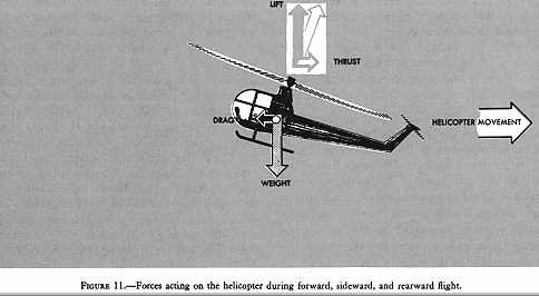 |
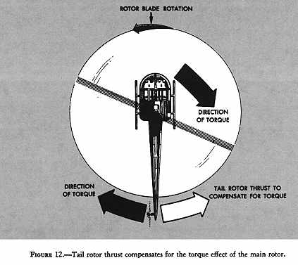
Figure 12 - Tail rotor thrust compensates for the torque effect of the main rotor.
Torque - Newton's third law of motion states, "To every action there is an equal and opposite reaction." As the main rotor of a helicopter turns in one direction, the fuselage tends to rotate in the opposite direction (fig. 12). This tendency for the fuselage to rotate is called torque. Since torque effect on the fuselage is a direct result of engine power supplied to the main rotor, any change in engine power brings about a corresponding change in torque effect. The greater the engine power, the greater the torque effect. Since there is no engine power being supplied to the main rotor during autorotation, there is no torque reaction during autorotation.
Auxiliary rotor - The force that compensates for torque and keeps the fuselage from turning in the direction opposite to the main rotor is produced by means of an auxiliary rotor located on the end of the tail boom. This auxiliary rotor, generally referred to as a tail rotor, or antitorque rotor, produces thrust in the direction opposite to torque reaction developed by the main rotor (fig. 12). Foot pedals in the cockpit permit the pilot to increase or decrease tail rotor thrust, as needed, to neutralize torque effect.
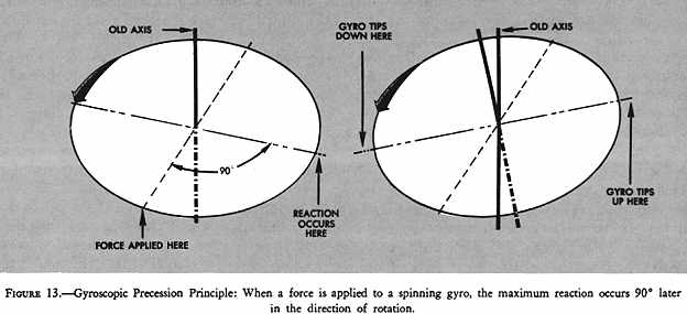
Gyroscopic precession - The spinning main rotor of a helicopter acts like a gyroscope. As such, it has the properties of gyroscopic action, one of which is precession. Gyroscopic precession is the resultant action or deflection of a spinning object when a force is applied to this object. This action occurs approximately 90° in the direction of rotation from the point where the force is applied (fig. 13). Through the use of this principle, the tip-path plane of the main rotor may be tilted from the horizontal.
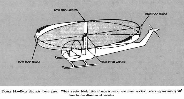
The movement of the cyclic pitch control in a two-bladed rotor system increases the angle of attack of one rotor blade with the result that a greater lifting force is applied at this point in the plane of rotation. This same control movement simultaneously decreases the angle of attack of the other blade a like amount, thus decreasing the lifting force applied at this point in the plane of rotation. The blade with the increased angle of attack tends to rise; the blade with the decreased angle of attack tends to lower. However, because of the gyroscopic precession property, the blades do not rise or lower to maximum deflection until a point approximately 90° later in the plane of rotation. In the illustration (fig. 14), the retreating blade angle of attack is increased and the advancing blade angle of attack is decreased resulting in a tipping forward of the tip-path plane, since maximum deflection takes place 90° later when the blades are at the rear and front respectively.
Figure 13 - Gyroscopic Precession Principle: When a force is applied to a spinning gyro, the maximum reaction occurs 90° later in the direction of rotation.
In a three-bladed rotor, the movement of the cyclic pitch control changes the angle of attack of each blade an appropriate amount so that the end result is the same - a tipping forward of the tip-path plane when the maximum change in angle of attack is made as each blade passes the same points at which the maximum increase and decrease are made in the illustration (fig. 14) for the two-bladed rotor. As each blade passes the 90° position on the left, the maximum increase in angle of attack occurs. As each blade passes the 90° position to the right, the maximum decrease in angle of attack occurs. Maximum deflection takes place 90° later - maximum upward deflection at the rear and maximum downward deflection at the front - and the tip-path plane tips forward.
Figure 14 - Rotor disc acts like a gyro. When a rotor blade pitch change is made, maximum reactions occurs approximately 90° later in the direction of rotation.
Dissymmetry of lift - The area within the tip-path plane of the main rotor is known as the disc area or rotor disc. When hovering in still air, lift created by the rotor blades at all corresponding positions around the rotor disc is equal. Dissymmetry of lift is created by horizontal flight or by wind during hovering flight, and is the difference in lift that exists between the advancing blade half of the disc area and the retreating blade half.
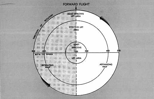
At normal rotor operating RPM and zero airspeed, the rotating blade-tip speed of most helicopter main rotors is approximately 400 miles per hour. When hovering in a no-wind condition, the speed of the relative wind at the blade tips is the same throughout the tip-path plane (fig. 15, bottom). The speed of the relative wind at any specific point along the rotor blade will be the same throughout the tip-path plane; however, the speed is reduced as this point moves closer to the rotor hub as indicated by the two inner circles. As the helicopter moves into forward flight, the relative wind moving over each rotor blade becomes a combination of the rotational speed of the rotor and the forward movement of the helicopter (fig. 15, top). At the 90° position on the right side, the advancing blade has the combined speed of the blade velocity plus the speed of the helicopter. At the 90° position on the left side, the retreating blade speed is the blade velocity less the speed of the helicopter. (In the illustration, the helicopter is assumed to have a forward airspeed of 100 miles per hour.) In other words, the relative windspeed is at a maximum at the 90° position on the right side and at a minimum at the 90° position on the left side.
Earlier in this handbook, the statement was made that for any given angle of attack, lift increases as the velocity of the airflow over the airfoil increases. It is apparent that the lift over the advancing blade half of the rotor disc will be greater than the lift over the retreating blade half during horizontal flight, or when hovering in a wind unless some compensation is made. It is equally apparent that the helicopter will roll to the left unless some compensation is made. The compensation made to equalize the lift over the two halves of the rotor disc is blade flapping and cyclic feathering.
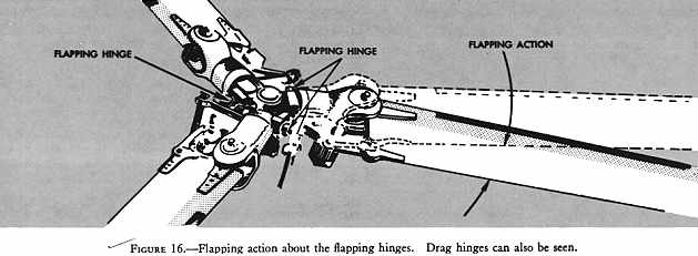
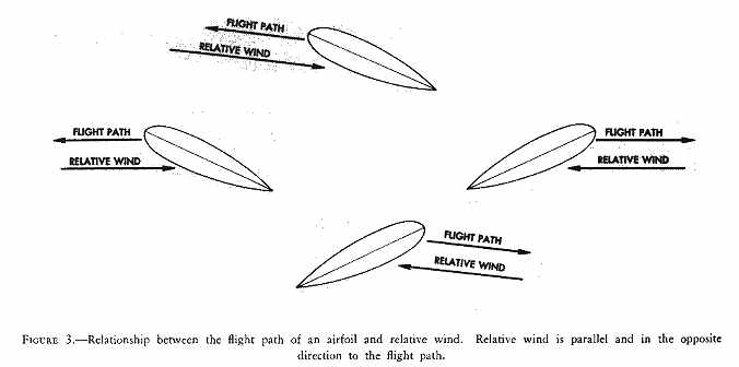
Blade flapping - In a three-bladed rotor system, the rotor blades are attached to the rotor hub by a horizontal hinge which permits the blades to move in a vertical plane, i.e., flap up or down, as they rotate (fig. 16). In forward flight and assuming that the blade-pitch angle remains constant, the increased lift on the advancing blade will cause the blade to flap up decreasing the angle of attack because the relative wind will change from a horizontal direction to more of a downward direction. The decreased lift on the retreating blade will cause the blade to flap down increasing the angle of attack because the relative wind changes from a horizontal direction to more of an upward direction (fig. 3). The combination of decreased angle of attack on the advancing blade and increased angle of attack on the retreating blade through blade flapping action tends to equalize the lift over the two halves of the rotor disc.
In a two-bladed system, the blades flap as a unit. As the advancing blade flaps up due to the increased lift, the retreating blade flaps down due to the decreased lift. The change in angle of attack on each blade brought about by this flapping action tends to equalize the lift over the two halves of the rotor disc.
The position of the cyclic pitch control in forward flight also causes a decrease in angle of attack on the advancing blade and an increase in angle of attack on the retreating blade. This, together with blade flapping, equalizes lift over the two halves of the rotor disc.
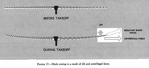
Coning - Coning is the upward bending of the blades caused by the combined forces of lift and centrifugal force. Before takeoff, the blades rotate in a plane nearly perpendicular to the rotor mast, since centrifugal force is the major force acting on them (fig. 17).
As a vertical takeoff is made, two major forces are acting at the same time - centrifugal force acting outward perpendicular to the rotor mast and lift acting upward and parallel to the mast. The result of these two forces is that the blades assume a conical path instead of remaining in the plane perpendicular to the mast (fig. 17).
Coning results in blade bending in a semirigid rotor; in an articulated rotor, the blades assume an upward angle through movement about the flapping hinges.
Figure 15 - Comparison of rotor blade speeds for
the advancing blade and retreating blade during hovering and forward flight.
 |
|
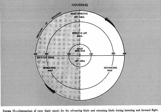 |
Figure 16 - Flapping action about the flapping hinges. Drag hinges can also be seen.
Figure 17 - Blade coning is a result of lift and centrifugal force.
Axis of rotation - The axis of rotation of a helicopter rotor is the imaginary line about which the rotor rotates. It is represented by a line drawn through the center of, and perpendicular to, the tip-path plane. It is not to be confused with the rotor mast. The only time the rotor axis of rotation coincides with the rotor mast is when the tip-path plane is perpendicular to the rotor mast (fig. 18).
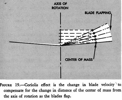
Coriolis effect - When a rotor blade of a three-bladed rotor system flaps upward, the center of mass of that blade moves closer to the axis of rotation and blade acceleration takes place. Conversely, when that blade flaps downward, its center of mass moves further from the axis of rotation and blade deceleration takes place (fig. 19). (Keep in mind, that due to coning, the rotor blade will not flap below a plane passing through the rotor hub and perpendicular to the axis of rotation.) The acceleration and deceleration actions (often referred to as leading, lagging, or hunting) of the rotor blades are absorbed by either dampers or the blade structure itself, depending upon the design of the rotor system.
Two-bladed rotor systems are normally subject to CORIOLIS EFFECT to a much lesser degree than are three-bladed systems since the blades are generally "underslung" with respect to the rotor hub, and the change in the distance of the center of mass from the axis of rotation is small. The hunting action is absorbed by the blades through bending. If a two-bladed rotor system is not "underslung," it will be subject to CORIOLIS EFFECT comparable to that of a fully articulated system.
Figure 18 - The axis of rotation is the imaginary line about which the rotor rotates and is perpendicular to the tip-path plane.
Figure 19 - Coriolis effect is the change in blade velocity to compensate for the change in distance of the center of mass from the axis of rotation as the blades flap.
CORIOLIS EFFECT might be compared to spinning skaters. When they extend their arms, their rotation slows down because their center of mass moves farther from their axis of rotation. When their arms are retracted, their rotation speeds up because their center of mass moves closer to their axis of rotation.
The tendency of a rotor blade to increase or decrease its velocity in its plane of rotation due to mass movement is known as CORIOLIS EFFECT, named for the mathematician who made studies of forces generated by radial movements of mass on a rotating disc.
Translating tendency or drift - The entire helicopter has a tendency to move in the direction of tail rotor thrust (to the right) when hovering. This movement is often referred to as "drift." To counteract this drift, the rotor mast in some helicopters is rigged slightly to the left side so that the tip-path plane has a built-in tilt to the left, thus producing a small sideward thrust. In other helicopters, drift is overcome by rigging the cyclic pitch system to give the required amount of tilt to the tip-path plane (fig. 20).
Figure 20 - Drift, cause by tail rotor thrust, is compensated for by rigging the mast or cyclic pitch system to have a built-in tilt of the tip-path plane to the left.
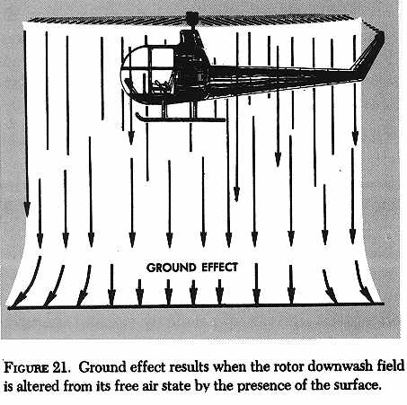
Ground effect - When a helicopter is operated near the surface, the downwash velocity created by the rotor blades cannot be fully developed due to the proximity of the surface. This restraint of rotor downwash occurs as the helicopter reaches a relatively low altitude - usually less than one rotor diameter above the surface (fig. 21).
As the downwash velocity is reduced, the induced angle of attack of each rotor blade is reduced and the lift vector becomes more vertical. Simultaneously, a reduction in induced drag occurs. In addition, as the induced angle of attack is reduced, the angle of attack generating lift is increased. The net result of these actions is a beneficial increase in lift and a lower power requirement to support a given weight.
Figure 21 - Ground effect results when the rotor downwash field is altered from its free air state by the presence of the surface.
Translational lift - Translational lift is that additional lift obtained when entering horizontal flight, due to the increased efficiency of the rotor system. The rotor system produces more lift in forward flight because the higher inflow velocity supplies the rotor disc with a greater mass of air per unit time upon which to work than it receives while hovering. Translational lift is present with any horizontal movement although the increase will not be noticeable until airspeed reaches approximately 15 miles per hour. The additional lift available at this speed is referred to as "effective translational lift" and is easily recognized in actual flight by the increased performance of the helicopter.
Since translational lift depends upon airspeed rather than groundspeed, the helicopter does not have to be in horizontal flight to be affected. Translational lift will be present during hovering flight in a wind - the amount being proportional to the wind velocity - and effective translational lift will be present when hovering in winds of 15 MPH or more.
Transverse flow effect - In forward flight, air passing through the rear portion of the rotor disc has a higher downwash velocity than air passing through the forward portion. This is because the air passing through the rear portion has been accelerated for a longer period of time than the air passing through the forward portion. This increased downwash velocity at the rear of the disc decreases the angle of attack and blade lift, hence in combination with gyroscopic precession, causes the rotor disc to tilt to the right (the advancing side). The lift on the forward part of the rotor disc is greater than on the rearward part. According to the principle of gyroscopic precession, maximum deflection of the rotor blades occurs 90° later in the direction of rotation. This means that the rotor blades will reach maximum upward deflection on the left side and maximum downward deflection on the right side. This transverse flow effect is responsible for the major portion of the lateral cyclic stick control required to trim the helicopter at low speed.
Pendular action - Since the fuselage of the helicopter is suspended from a single point and has considerable mass, it is free to oscillate either longitudinally or laterally in the same way as a pendulum (fig. 22). This pendular action can be exaggerated by overcontrolling; therefore, control stick movements should be moderate.
AUTOROTATION
Autorotation is the term used for the flight condition during which no engine power is supplied and the main rotor is driven only by the action of the relative wind. It is the means of safely landing a helicopter after engine failure or certain other emergencies. The helicopter transmission or power train is designed so that the engine, when it stops, is automatically disengaged from the main rotor system to allow the main rotor to rotate freely in its original direction. For obvious reasons, this autorotational capability is not only a most desirable characteristic but is indeed a capability required of all helicopters before FAA certification is granted.
igure 22 - Since the helicopter is suspended from the rotor mast head, it acts much like a pendulum.
When engine power is being supplied to the main rotor, the flow of air is downward through the rotor. When engine power is not being supplied to the main rotor, that is, when the helicopter is in autorotation, the flow of air is upward through the rotor. It is this upward flow of air that causes the rotor to continue turning after engine failure.
The portion of the rotor blade that produces the forces that cause the rotor to turn when the engine is no longer supplying power to the rotor is that portion between approximately 25 percent and 70 percent of the radius outward from the center. This portion is often referred to as the "autorotative or driving region" (fig. 23). Aerodynamic forces along this portion of the blade tend to speed up the blade rotation.
The inner 25 percent of the rotor blade, referred to as the "stall region," operates above its maximum angle of attack (stall angle), thereby contributing little lift but considerable drag which tends to slow the blade rotation.
The outer 30 percent of the rotor blade is known as the "propeller or driven region." Aerodynamic forces here result in a small drag force which tends to slow the tip portion of the blade.
The aerodynamic regions as described above are for vertical autorotations. During forward flight autorotations, these regions are displaced across the rotor disc to the left (fig. 23).
Rotor RPM during autorotation
Rotor RPM stabilizes when the autorotative forces (thrust) of the "driving region" and the antiautorotative forces (drag) of the "driven region" and "stall region" are equal. Assume that rotor RPM has been increased by entering an updraft; a general lessening in angle of attack will follow along the entire blade. This produces a change in aerodynamic force vectors which results in an overall decrease in the autorotative forces and the rotor tends to slow down. If rotor RPM has been decreased by entering a downdraft, autorotative forces will tend to accelerate the rotor back to its equilibrium RPM.
Figure 23 - Contribution of various portions of the rotor disc to the maintenance of RPM during an autorotation - vertical autorotation (left); forward flight autorotation (right).
Assuming a constant collective pitch setting, that is, a constant rotor blade pitch angle, an overall greater angle of attack of the rotor disc (as in a flare) increases rotor RPM; a lessening in overall angle of attack (such as "pushing over" into a descent) decreases rotor RPM.
Flares during autorotation
Forward speed during autorotative descent permits a pilot to incline the rotor disc rearward, thus causing a flare. The additional induced lift created by the greater volume of air momentarily checks forward speed as well as descent. The greater volume of air acting on the rotor disc will normally increase rotor RPM during the flare. As the forward speed and descent rate near zero, the upward flow of air has practically ceased and rotor RPM again decreases; the helicopter settles at a slightly increased rate but with reduced forward speed. The flare enables the pilot to make an emergency landing on a definite spot with little or no landing roll or skid.