Electricity, when properly controlled, is of vital importance to the operation of aircraft. When it is not properly controlled, it can become dangerous and destructive. It can destroy aircraft components or complete aircraft; it can injure personnel and even cause their death.
It is of the greatest importance, then, that all necessary precautions be taken to protect the electrical circuits and units in the aircraft and to keep this force under proper control at all times.
Protective Devices
When an aircraft is built, the greatest care is taken to ensure that each electrical circuit is fully insulated from all others so that the current in a circuit will follow its intended individual path. Once the aircraft is put into service, however, there are many things that can happen to alter the original circuitry. Some of these changes can cause serious trouble if not detected and corrected in time.
Perhaps the most serious trouble in a circuit is a direct short. The term, "direct short," describes a situation in which some point in the circuit, where full system voltage is present, comes in direct contact with the ground or return side of the circuit. This establishes a path for current flow that contains no resistance other than that present in the wires carrying the current, and these wires have very little resistance.
According to Ohm's law, if the resistance in a circuit is small, the current will be great. When a direct short occurs, there will be an extremely heavy current flowing through the wires. Suppose, for instance, that the two leads from a battery to a motor came in contact with each other. Not only would the motor stop running because of the current going through the short, but the battery would become discharged quickly (perhaps destroyed); there would also be danger of fire.
The battery cables in this example would be very large wires, capable of carrying very heavy currents. Most wires used in aircraft electrical circuits are considerably smaller and their current carrying capacity is quite limited. The size of the wires used in any given circuit is determined by the amount of current the wires are expected to carry under normal operating conditions. Any current flow greatly in excess of normal, such as the case of a direct short, would cause a rapid generation of heat.
If the excessive current flow caused by the short is left unchecked, the heat in the wire will continue to increase until something gives way. Perhaps a portion of the wire will melt and open the circuit so that nothing is damaged other than the wires involved. The probability exists, however, that much greater damage would result. The heat in the wires could char and burn their insulation and that of other wires bundled with them, which could cause more shorts.
FIGURE 8-111. Nickel-cadmium troubleshooting chart.
If a fuel or oil leak is near any of the hot wires, a disastrous fire might be started. To protect aircraft electrical systems from damage and failure caused by excessive current, several kinds of protective devices are installed in the systems. Fuses, circuit breakers, and thermal protectors are used for this purpose.
Circuit protective devices, as the name implies, all have a common purpose - to protect the units and the wires in the circuit. Some are designed primarily to protect the wiring and to open the circuit in such a way as to stop the current flow when the current becomes greater than the wires can safely carry. Other devices are designed to protect a unit in the circuit by stopping the current flow to it when the unit becomes excessively warm.
Fuses
A fuse is a strip of metal that will melt when current in excess of its carefully determined capacity flows through it. The fuse is installed in the circuit so that all the current in the circuit passes through it. In most fuses, the strip of metal is made of an alloy of tin and bismuth. Other fuses are made of copper and are called current limiters; these are used primarily to sectionalize an aircraft circuit.
A fuse melts and breaks the circuit when the current exceeds the rated capacity of the fuse, but a current limiter will stand a considerable overload for a short period of time. Since the fuse is intended to protect the circuit, it is quite important that its capacity match the needs of the circuit in which it is used. When a fuse is replaced, the applicable manufacturer's instructions should be consulted to be sure a fuse of the correct type and capacity is installed. Fuses are installed in two type fuse holders in aircraft. "Plug-in holders" are used for small type and low capacity fuses. "Clip" type holders are used for heavy high capacity fuses and current limiters.
Circuit Breakers
A circuit breaker is designed to break the circuit and stop the current flow when the current exceeds a predetermined value. It is commonly used in place of a fuse and may sometimes eliminate the need for a switch. A circuit breaker differs from a fuse in that it "trips" to break the circuit and it may be reset, while a fuse melts and must be replaced.
There are several types of circuit breakers in general use in aircraft systems. One is a magnetic type. When excessive current flows in the circuit, it makes an electromagnet strong enough to move a small armature which trips the breaker. Another type is the thermal overload switch or breaker. This consists of a bimetallic strip which, when it becomes overheated from excessive current, bends away from a catch on the switch lever and permits the switch to trip open.
Most circuit breakers must be reset by hand. When the circuit breaker is reset, if the overload condition still exists, the circuit breaker will trip again to prevent damage to the circuit.
Thermal Protectors
A thermal protector, or switch, is used to protect a motor. It is designed to open the circuit automatically whenever the temperature of the motor becomes excessively high. It has two positions, open and closed. The most common use for a thermal switch is to keep a motor from overheating. If a malfunction in the motor causes it to overheat, the thermal switch will break the circuit intermittently.
The thermal switch contains a bimetallic disk, or strip, which bends and breaks the circuit when it is heated. This occurs because one of the metals expands more than the other when they are subjected to the same temperature. When the strip or disk cools, the metals contract and the strip returns to its original position and closes the circuit.
Control Devices
The units in the electrical circuits in an aircraft are not all intended to operate continuously or automatically. Most of them are meant to operate at certain times, under certain conditions, to perform very definite functions. There must be some means of controlling their operation. Either a switch or a relay, or both, may be included in the circuit for this purpose.
SWITCHES
Switches control the current flow in most aircraft electrical circuits. A switch is used to start, to stop, or to change the direction of the current flow in the circuit. The switch in each circuit must be able to carry the normal current of the circuit and must be insulated heavily enough for the voltage of the circuit.
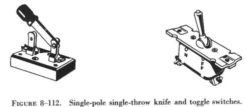
Knife switches are seldom used on aircraft. They are included here to simplify the operation of the toggle switch. Toggle switches operate much the same as knife switches, but their moving parts are enclosed. They are used in aircraft circuits more than any other kind of switch.
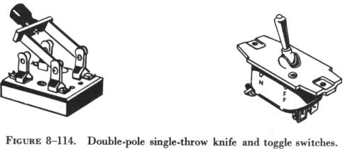
Toggle switches, as well as some other type of switches, are designated by the number of poles, throws, and positions they have. A pole of a switch is its movable blade or contactor. The number of poles is equal to the number of circuits, or paths for current flow, that can be completed through the switch at any one time. The throw of a switch indicates the number of circuits, or paths for current, that it is possible to complete through the switch with each pole or contactor. The number of positions a switch has is the number of places at which the operating device (toggle, plunger, etc.) will come to rest and at the same time open or close one or more circuits.
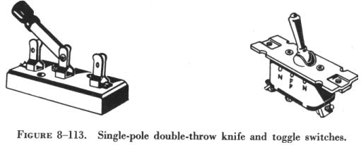
As shown in figure 8-112, when it is possible to complete only one circuit through a switch, the switch is a single pole single throw (spst) switch. A single pole switch through which two circuits can be completed (not at the same time) is a single pole double throw (spdt) switch. (See figure 8-113.)
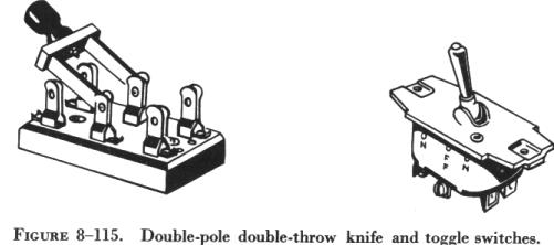
A double pole switch that can complete two circuits, one circuit at a time through each pole, is a double pole double throw (dpdt) switch. Both a knife and a toggle switch illustrating this type of switch are shown in figure 8-115.
The schematic representations for the most commonly used switches are shown in figure 8-116.
A toggle switch that is spring loaded to the OFF position and must be held in the ON position to complete the circuit is a momentary contact two position switch. One that will come to rest at either of two positions, opening the circuit in one position and closing it in another, is a two position switch. A toggle switch that will come to rest at any one of three positions is a three position switch.
A switch that stays open, except when it is held in the closed position,
is a normally open switch (usually identified as NO). One that stays closed,
except when it is held in the open position, is a normally closed switch
(NC). Both kinds are spring loaded to their normal position and will return
to that position as soon as they are released.
 |
Pushbutton Switches
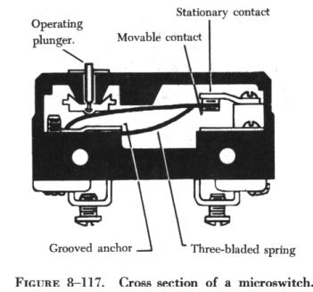
Pushbutton switches have one stationary contact and one movable contact. The movable contact is attached to the push button. The push button is either an insulator itself or is insulated from the contact. This switch is springloaded and designed for momentary contact. Microswitches A microswitch will open or close a circuit with a very small movement of the tripping device (1/16 inch or less). This is what gives the switch its name, since micro means small. Microswitches are usually pushbutton switches. They are used primarily as limit switches to provide automatic control of landing gears, actuator motors, and the like. The diagram in figure 8-117 shows a normally closed microswitch in cross section and illustrates how these switches operate. When the operating plunger is pressed in, the spring and the movable contact are pushed, opening the contacts and the circuit. |
Rotary Selector Switches
A rotary selector switch takes the place of several switches. As shown in figure 8-118, when the knob of the switch is rotated, the switch opens one circuit and closes another. Ignition switches and voltmeter selector switches are typical examples of this kind of switch.
Relays
Relays, or relay switches, are used for remote control of circuits carrying heavy currents, A relay is connected in the circuit between the unit controlled and the nearest source of power (or power bus bar) so that the cables carrying heavy current will be as short as possible.
A relay switch consists of a coil, or solenoid, an iron core, and both fixed and movable contacts. A small wire connects one of the coil terminals (which is insulated from the housing) to the source of power through a control switch usually located in the cockpit. The other coil terminal is usually grounded to the housing. When the control switch is closed, an electromagnetic field is set up around the coil.
In one type of relay switch, an iron core is fixed firmly in place inside
the coil. When the control switch is closed, the core is magnetized and
pulls a soft iron armature toward it, closing the main contacts. The contacts
are spring loaded to the open position as shown in figure
8-119. When the control switch is turned off, the magnetic field collapses
and the spring opens the contacts.
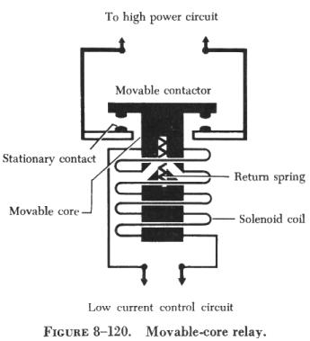
| In another type of relay switch, part of the core is movable. A spring
holds the movable part a short distance away from the fixed part, as illustrated
in figure 8-120. When the coil is energized, the magnetic field tries to
pull the movable part of the core into the coil. This pull overcomes the
spring tension. As the core moves inward, it brings the movable contacts,
which are attached to but insulated from it, down against the stationary
contacts. This completes the main circuit. When the control switch is turned
off, the magnetic field collapses and the spring returns the movable core
to its original position, opening the main contacts.
Relays vary in construction details according to their intended use. When selecting a relay to be installed in a circuit, make sure it is designed for the job it is intended to do. Some relay switches are made to operate continuously, while others are designed to operate only intermittently. The starter relay switch is made to operate intermittently and would overheat if used continuously. The battery relay switch can be operated continuously because its coil has a fairly high resistance which prevents overheating. |
 |
In a circuit carrying a large current, the more quickly the circuit is opened the less it will arc at the relay, and the less the switch contacts will be burned. Relays used in circuits with large motors have strong return springs to open the circuit quickly.
Most of the relays use in the ac circuitry of an aircraft are energized by dc current. These devices will be discussed, as necessary, in the appropriate areas covering alternating current devices.