General
Ordinarily, a machine is thought of as a complex device, such as an internal combustion engine or a typewriter. These are machines, but so is a hammer, a screwdriver, or a wheel. A machine is any device with which work may be accomplished. Machines are used to transform energy, as in the case of a generator transforming mechanical energy into electrical energy. Machines are used to transfer energy from one place to another, as in the examples of the connecting rods, crankshaft, and reduction gears transferring energy from an aircraft's engine to its propeller.
Another use of machines is to multiply force; for example, a system of pulleys may be used to lift a heavy load. The pulley system enables the load to be raised by exerting a force which is smaller than the weight of the load.
Machines are also used to multiply speed. A good example is the bicycle, by which speed can be gained by exerting a greater force.
Finally, machines can be used to change the direction of a force. An example of this use is the flag hoist. A downward force on one side of the rope exerts an upward force on the other side, raising the flag toward the top of the pole.
There are only six simple machines. They are the lever, the pulley, the wheel and axle, the inclined plane, the screw, and the gear. However, physicists recognize only two basic principles in machines; namely, the lever and the inclined plane. The wheel and axle, the block and tackle, and gears may be considered levers. The wedge and the screw use the principle of the inclined plane.
An understanding of the principles of simple machines provides a necessary foundation for the study of compound machines, which are combinations of two or more simple machines.
The Lever
The simplest machine, and perhaps the most familiar one, is the lever. A seesaw is a familiar example of a lever in which one weight balances the other.
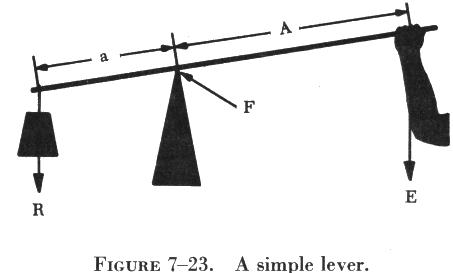
There are three basic parts in all levers; namely, the fulcrum "F," a force or effort "E," and a resistance "R." Shown in figure 7-23 are the pivotal point "F" (fulcrum); the effort "E," which is applied at a distance "A" from the fulcrum; and a resistance "R," which acts at a distance "a" from the fulcrum. Distances "A" and "a" are the lever arms.
Classes of Levers
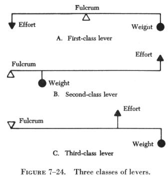
The three classes of levers are illustrated in figure 7-24. The location of the fulcrum (the fixed or pivot point) with relation to the resistance (or weight) and the effort determines the lever class.
First Class Levers
In the first class lever (A of figure 7-24), the fulcrum is located between the effort and the resistance. As mentioned earlier, the seesaw is a good example of the first class lever. The amount of weight and the distance from the fulcrum can be varied to suit the need. Another good example is the oars of a rowboat. Notice that the fisherman in figure 7-25 applies his effort on the handles of the oars. The oarlock acts as the fulcrum, and the water acts as the resistance to be overcome. In this case, as in A of figure 7-24, the force is applied on one side of the fulcrum, and the resistance to be overcome is applied to the opposite side; hence, this is a first class lever. Crowbars, shears, and pliers are common examples of this class of lever.
Second Class Levers
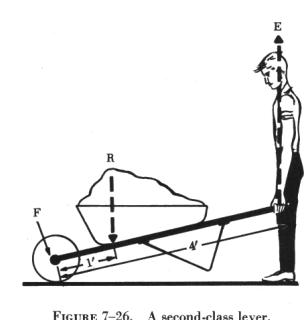
The second class lever (B of figure 7-24) has the fulcrum at one end; the effort is applied at the other end. The resistance is somewhere between these points. The wheelbarrow in figure 7-26 is a good example of a second class lever.
Both first and second class levers are commonly used to help in overcoming big resistances with a relatively small effort.
Third Class Levers
There are occasions when it is desirable to speed up the movement of the resistance even though a large amount of effort must be used. Levers that help accomplish this are third class levers. As shown in C of figure 7-24, the fulcrum is at one end of the lever and the weight or resistance to be overcome is at the other end, with the effort applied at some point between. Third class levers are easily recognized because the effort is applied between the fulcrum and the resistance. This is illustrated by the diagram in figure 7-27.
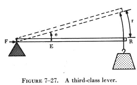
While point "E" is moving the short distance "e," the resistance "R" moves a greater distance "r." The speed of "R" must be greater than that of "E," since "R" covers a greater distance in the same length of time.
The human arm (figure 7-28) is a third class lever. It is this lever action that makes possible the quick flexing of the arms. Note that the elbow is the fulcrum. The biceps muscle, which is tied onto the forearm below the elbow, applies the effort; and the hand, is the resistance. Third class levers should be used to gain speed, rather than to move heavy loads.
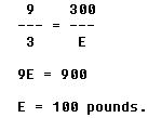
The forces required to operate machines, as well as the forces they will exert, can be easily determined. Consider the iron bar used as a first class lever in figure 7-29. The bar is 9 feet long and is used to raise a 300 pound weight. Assume that a maximum of 100 pounds is available to lift the weight. If a fulcrum "F" is placed 2 feet from the center of the weight, a 6 foot length of the bar becomes the effort arm. This 6 foot length is three times as long as the distance from the fulcrum to the center of the weight. With a 100 pound effort at "E", the 300 pound weight can be lifted, since the length of the effort arm has multiplied the effort three times. This is an example of the direct relationship between lengths of lever arms and the forces acting on the arms.
This relationship can be stated in general terms: The length of the effort arm is the same number of times greater than the length of the resistance arm as the resistance to be overcome is greater than the effort that must be applied.
The mathematical equation for this relationship is:

where:
L = length of effort arm.
l = length of resistance arm.
R = resistance weight or force.
E = effort force.
Remember that all distances must be in the same units, and all forces must also be in the same units.
In figure 7-30 another first class lever problem is illustrated: To pry up the lid of the paint can with a 6 inch bar when the average force holding the lid is assumed to be 50 pounds. If the distance from the edge of the can to the edge of the cover is 1 inch, what force must be applied to the end of the bar?
According to the formula:
![]()
Here, L = 5 inches; l = 1 inch; R = 50 pounds, and E is unknown. Substitute the numbers in their proper places; then
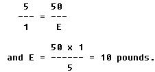
A force of 10 pounds is required.
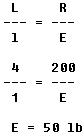
The same general formula applies for second class levers; but it is important to measure the proper lengths of the effort arm and the resistance arm. Referring to figure 7-26, the length of the wheelbarrow handles from the axle of the wheel (which is the fulcrum) to the grip is 4 feet. This is an effort arm 4 feet in length. The center of the load of sand is 1 foot from the axle; thus, the length of the resistance arm is 1 foot.
By substituting in the formula,
A third class lever problem is illustrated in figure 7-28. With one hand, a weight of 10 pounds is to be lifted. If the biceps muscle is attached to the forearm 1 inch below the elbow, and the distance from the elbow to the palm of the hand is 18 inches, what pull must the muscle exert in order to hold the weight and flex the arm at the elbow? By substituting in the formula,
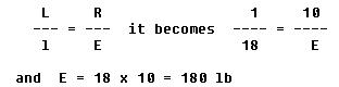
The muscle must exert a 180 pound pull to hold up the 10 pound weight. This illustrates that the biceps muscle is poorly arranged for lifting or pulling. It also illustrates that third class levers should be used primarily to speed up motion of a resistance.
Mechanical Advantage of Levers
Levers may provide mechanical advantages, since they can be applied in such manner that they can magnify an applied force. This is true of first and second class levers. The third class lever provides what is called a fractional disadvantage, i.e., one in which a greater force is required than the force of the load lifted.
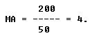
In the problem involving the wheelbarrow (figure 7-26), a 50 pound pull overcomes the 200 pound weight of the sand. In this case, the effort was magnified four times. Thus the mechanical advantage gained by using the wheelbarrow is 4.
Expressing the same idea in mathematical terms,
Resistance
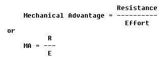
Thus, in the case of the wheelbarrow,
This rule applies to all machines.
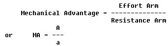
Mechanical advantage of levers may also be found by dividing the length of the effort arm "A" by the length of the resistance arm "a." Stated as a formula, this reads:
How does this apply to third class levers? If a muscle pulls with a force of 1,800 pounds in order to lift a 100 pound projectile, a mechanical advantage of 100/1,800 or 1/18 is obtained. This is a fractional disadvantage, since it is less than 1.
The Inclined Plane
The inclined plane is a simple machine that facilitates the raising or lowering of heavy objects by application of a small force over a relatively long distance. Some familiar examples of the inclined plane are mountain highways and cattle loading ramps.
The inclined plane permits a large resistance to be overcome by application of a small force through a longer distance than the load is to be raised. In figure 7-31, a 300 pound barrel is being rolled up a ramp to the bed of a truck, 3 feet above the sidewalk. The ramp is 9 feet long.
Without the ramp, a force of 300 pounds, applied straight up through the 3 foot distance, would be required to load the barrel. With the ramp, a force can be applied over the entire 9 feet of the ramp as the barrel is rolled slowly up to a height of 3 feet. It can be determined by observation that a force of only three-ninths of 300, or 100 pounds, will be required to raise the barrel by using an inclined plane. This can also be determined mathematically, using the formula,

where:
L = length of the ramp, measured along the slope.
l = height of the ramp.
R = weight of object to be raised, or lowered.
E = force required to raise or lower object.
In this case, L = 9 ft; l = 3 ft; and R = 300 lb. Substituting these values in the formula,
Since the ramp is three times as long as its height, the mechanical advantage is three. The theoretical mechanical advantage is found by dividing the total distance through which the effort is exerted by the vertical distance through which the load is raised or lowered.
The Wedge
The wedge is a special application of the inclined plane. The blades of knives, axes, hatchets, and chisels act as wedges when they are forced into a piece of wood. The wedge is two inclined planes, set base-to-base. By driving the wedge full length into the material to be cut or split, the material is forced apart a distance equal to the width of the broad end of the wedge (see figure 7-32).
Long, slim wedges have high mechanical advantages. For example, the wedge in figure 7-32 has a mechanical advantage of 6. The greatest value of wedges is found in situations where other simple machines cannot be used. For example, imagine trying to pull a log apart with a system of pulleys.
The Pulley
Pulleys are simple machines in the form of a wheel mounted on a fixed axis and supported by a frame. The wheel, or disk, is normally grooved to accommodate a rope. The wheel is sometimes referred to as a "sheave" (sometimes "sheaf"). The frame that supports the wheel is called a block. A block and tackle consists of a pair of blocks. Each block contains one or more pulleys and a rope connecting the pulley(s) of each block.
Single Fixed Pulley
A single fixed pulley is really a first class lever with equal arms. The arms "EF" and "FR" in figure 7-33 are equal; hence the mechanical advantage is one. Thus, the force of the pull on the rope must be equal to the weight of the object being lifted. The only advantage of a single fixed pulley is to change the direction of the force, or pull on the rope.
A single pulley can be used to magnify the force exerted. In figure 7-34 the pulley is not fixed, and the rope is doubled because it supports a 200 pound weight. Used in this manner, a single block and tackle can lift the 200 pound weight with a 100 pound pull, since each half of the rope (tackle) carries one-half the total load. The mechanical advantage is 2, which can be verified by using the formula:
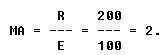
The single movable pulley used in the manner shown in figure 7-34 is a second class lever. To see this refer to figure 7-35. The effort "E" acts upward on the arm "EF," which is the diameter of the pulley. The resistance "R" acts downward on the arm "FR," which is the radius of the pulley. Since the diameter is twice the radius, the mechanical advantage is 2.
However, when the effort at "E" moves up 2 feet, the load at "R" is raised only 1 foot. This is true of all systems of block and tackle, for if a mechanical advantage is obtained, the length of rope passed through the hands is greater than the distance that the load is raised.
The mechanical advantage of a pulley system is found by measuring the resistance and the effort and dividing the amount of resistance by the effort. A shorthand method often used is simply to count the number of rope strands that move or support the movable block.