MAGNETICAMPLIFIERS
MAGNETIC AMPLIFIERS
| The magnetic amplifier is a control device being employed
at an increasing rate in many aircraft electrical and electronic systems.
This is because of its ruggedness, stability, and safety in comparison
to vacuum tubes.
The principles on which the magnetic amplifier operates can best be
explained by reviewing the operation of a simple transformer. If an ac
voltage is applied to the primary of an iron core transformer, the iron
core will be magnetized and demagnetized at the same frequency as that
of the applied voltage. This, in turn, will induce a voltage in the transformer
secondary. The output voltage across the terminals of the secondary will
depend on the relationship of the number of turns in the primary and the
secondary of the transformer.
The iron core of the transformer has a saturation point after which
the application of a greater magnetic force will produce no change in the
intensity of magnetization. Hence, there will be no change in transformer
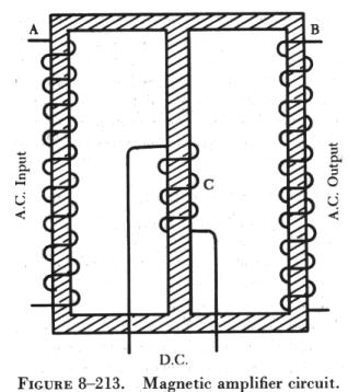
output, even if the input is greatly increased. The magnetic amplifier
circuit in figure 8-213 will be used to explain how a simple magnetic amplifier
functions. |
|
Assume that there is 1 ampere of current in coil A, which has 10 turns
of wire. If coil B has 10 turns of wire, an output of 1 ampere will be
obtained if coil B is properly loaded. By applying direct current to coil
C, the core of the magnetic amplifier coil can be further magnetized. Assume
that coil C has the proper number of turns and, upon the application of
30 milliamperes, that the core is magnetized to the point where 1 ampere
on coil A results in only 0.24 ampere output from coil B.
By making the dc input to coil C continuously variable from 0 to 30
milliamperes and maintaining an input of 1 ampere on coil A, it is possible
to control the output of coil B to any point between 0.24 ampere and 1
ampere in this example. The term "amplifier" is used for this arrangement
because, by use of a few milliamperes, control of an output of 1 or more
amperes is obtained.
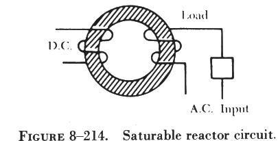
The same procedure can be used with the circuit shown in figure 8-214.
By controlling the extent of magnetization of the iron ring, it is possible
to control the amount of current flowing to the load, since the amount
of magnetization controls the impedance of the ac input winding. This type
of magnetic amplifier is called a simple saturable reactor circuit.
Adding a rectifier to such a circuit would remove half the cycle of
the ac input and permit a direct current to flow to the load. The amount
of dc flowing in the load circuit is controlled by a dc control winding
(sometimes referred to as bias). This type of magnetic amplifier is referred
to as being self-saturating.
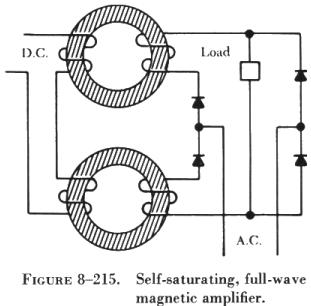
In order to use the full ac input power, a circuit such as that shown
in figure 8-215 may be used. This circuit uses a fullwave bridge rectifier.
The load will receive a controlled direct current by using the full ac
input. This type of circuit is known as a selfsaturating, fullwave magnetic
amplifier.
In figure 8-216 it is assumed that the dc control winding is supplied
by a variable source, such as a sensing circuit. In order to control such
a source and use its variations to control the ac output, it is necessary
to include another dc winding that has a constant value. This winding,
referred to as the reference winding, magnetizes the magnetic core in one
direction.
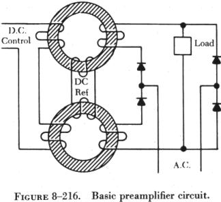
The dc control winding, acting in opposition to the reference winding,
either increases (degenerative) or decreases (regenerative) the magnetization
of the core to change the amount of current flowing through the load. This
is essentially a basic preamplifier.