METALCUTTINGTOOLS
METAL CUTTING TOOLS
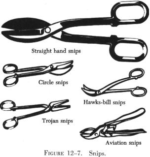
Hand Snips
| There are several kinds of hand snips, each of which serves a different
purpose. Straight, curved, hawksbill, and aviation snips are in common
use (figure 12-7). Straight snips are used for cutting straight lines when
the distance is not great enough to use a squaring shear and for cutting
the outside of a curve. The other types are used for cutting the inside
of curves or radii. Snips should never be used to cut heavy sheet metal.
Aviation snips are designed especially for cutting heat treated aluminum
alloy and stainless steel. They are also adaptable for enlarging small
holes. The blades have small teeth on the cutting edges and are shaped
for cutting very small circles and irregular outlines. The handles are
the compound leverage type, making it possible to cut material as thick
as 0.051 inch. Aviation snips are available in two types, those which cut
from right to left and those which cut from left to right. |
|
 |
Unlike the hacksaw, snips do not remove any material when the cut is
made, but minute fractures often occur along the cut. Therefore, cuts should
be made about one-thirty-second inch from the layout line and finished
by hand filing down to the line.
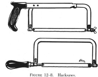
Hacksaws
The common hacksaw has a blade, a frame, and a handle. The handle can
be obtained in two styles, pistol grip and straight (figure 12-8).
Hacksaw blades have holes in both ends; they are mounted on pins attached
to the frame. When installing a blade in a hacksaw frame, mount the blade
with the teeth pointing forward, away from the handle. |
Blades are made of high grade tool steel or tungsten steel and are available
in sizes from 6 to 16 inches in length. The 10 inch blade is most commonly
used. There are two types, the all hard blade and the flexible blade. In
flexible blades, only the teeth are hardened.
Selection of the best blade for the job involves finding the right type
and pitch. An all hard blade is best for sawing brass, tool steel, cast
iron, and heavy cross-section materials. A flexible blade is usually best
for sawing hollow shapes and metals having a thin cross section.
The pitch of a blade indicates the number of teeth per inch. Pitches
of 14, 18, 24, and 32 teeth per inch are available. A blade with 14 teeth
per inch is preferred when cutting machine steel, cold rolled steel, or
structural steel. A blade with 18 teeth per inch is preferred for solid
stock aluminum, bearing metal, tool steel, and cast iron. Use a blade with
24 teeth per inch when cutting thick walled tubing, pipe, brass, copper,
channel, and angle iron. Use a 32 teeth per inch blade for cutting thin
walled tubing and sheet metal. When using a hacksaw, observe the following
procedures:
1. Select an appropriate saw blade for the job.
2. Assemble the blade in the frame so that the cutting edge of the teeth
points away from the handle.
3. Adjust tension of the blade in the frame to prevent the saw from
buckling and drifting.
4. Clamp the work in the vise in such a way that will provide as much
bearing surface as possible and will engage the greatest number of teeth.
5. Indicate the starting point by nicking the surface with the edge
of a file to break any sharp corner that might strip the teeth. This mark
will also aid in starting the saw at the proper place.
6. Hold the saw at an angle that will keep at least two teeth in contact
with the work at all times. Start the cut with a light, steady, forward
stroke just outside the cutting line. At the end of the stroke, relieve
the pressure and draw the blade back. (The cut is made on the forward stroke.)
7. After the first few strokes, make each stroke as long as the hacksaw
frame will allow. This will prevent the blade from overheating. Apply just
enough pressure on the forward stroke to cause each tooth to remove a small
amount of metal. The strokes should be long and steady with a speed not
more than 40 to 50 strokes per minute.
8. After completing the cut, remove chips from the blade, loosen tension
on the blade, and return the hacksaw to its proper place.
Chisels
A chisel is a hard steel cutting tool which can be used for cutting
and chipping any metal softer than the chisel itself. It can be used in
restricted areas and for such work as shearing rivets, or splitting seized
or damaged nuts from bolts (figure 12-9).
The size of a flat cold chisel is determined by the width of the cutting
edge. Lengths will vary, but chisels are seldom under 5 inches or over
8 inches long.
Chisels are usually made of eight sided tool steel bar stock, carefully
hardened and tempered. Since the cutting edge is slightly convex, the center
portion receives the greatest shock when cutting, and the weaker corners
are protected. The cutting angle should be 60° to 70° for general
use, such as for cutting wire, strap iron, or small bars and rods.
When using a chisel, hold it firmly in one hand. With the other hand,
strike the chisel head squarely with a ball peen hammer.
When cutting square corners or slots, a special cold chisel called a
cape chisel should be used. It is like a flat chisel except the cutting
edge is very narrow. It has the same cutting angle and is held and used
in the same manner as any other chisel.
Rounded or semicircular grooves and corners which have fillets should
be cut with a roundnose chisel. This chisel is also used to recenter a
drill which has moved away from its intended center.
The diamond point chisel is tapered square at the cutting end, then
ground at an angle to provide the sharp diamond point. It is used for cutting
B-grooves and inside sharp angles.
Files
Most files are made of high grade tool steels that are hardened and
tempered. Files are manufactured in a variety of shapes and sizes. They
are known either by the cross section, the general shape, or by their particular
use. The cuts of files must be considered when selecting them for various
types of work and materials.
| Files are used to square ends, file rounded comers, remove
burrs and slivers from metal, straighten uneven edges, file holes and slots,
and smooth rough edges.
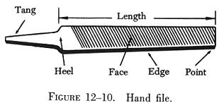
Files have three distinguishing features: (1) Their length, measured
exclusive of the tang (figure 12-10); (2) their kind or name, which has
reference to the relative coarseness of the teeth; and (3) their cut. |
 |
Files are usually made in two types of cuts, single cut and double cut.
The single cut file has a single row of teeth extending across the face
at an angle of 65° to 85° with the length of the file. The size
of the cuts depends on the coarseness of the file. The double cut file
has two rows of teeth which cross each other. For general work, the angle
of the first row is 40° to 45°. The first row is generally referred
to as "overcut," and the second row as "upcut"; the upcut is somewhat finer
and not so deep as the overcut.
Files - Care and Use
Files and rasps are cataloged in three ways:
Length. Measuring from the tip to the heel of the file. The tang
is never included in the length.
Shape. Refers to the physical configuration of the file (circular,
rectangular, or triangular or a variation thereof).
Cut. Refers to both the character of the teeth or the coarseness;
rough, coarse and bastard for use on heavier classes of work and second
cut, smooth and dead smooth for finishing work.
Most Commonly Used Files (see figure 12-11)
Hand files. These are parallel in width and tapered in thickness.
They have one safe edge (smooth edge) which permits filing in corners,
and on other work where a safe edge is required. Hand files are double
cut and used principally for finishing flat surfaces and similar work.
Flat files. These files are slightly tapered toward the point
in both width and thickness. They cut on both edges as well as on the sides.
They are the most common files in use. Flat files are double cut on both
sides and single cut on both edges.
Mill files. These are usually tapered slightly in thickness and
in width for about one-third of their length. The teeth are ordinarily
single cut. These files are used for drawfiling and to some extent for
filing soft metals.
Square files. These files may be tapered or blunt and are double
cut. They are used principally for filing slots and key seats, and for
surface filing.
Round or rattail files. These are circular in cross section and
may be either tapered or blunt and single or double cut. They are used
principally for filing circular openings or concave surfaces.
Triangular and Three square files. These files are triangular
in cross section. Triangular files are single cut and are used for filing
the gullet between saw teeth. Three square files, which are double cut,
may be used for filing internal angles, clearing out corners, and filing
taps and cutters.
Half round files. These files cut on both the flat and round
sides. They may be single or double cut. Their shape permits them to be
used where other files would be unsatisfactory.
Lead float files. These are especially designed for use on soft
metals. They are single cut and are made in various lengths.
Warding file - Rectangular in section and tapers to narrow point
as to width. Used for narrow space filing where other files cannot be used.
Knife file - Knife blade section. Used by tool and die makers
on work having acute angles.
Wood file - Same section as flat and half round files. Has coarser
teeth and is especially adaptable for use on wood.
Vixen (Curved tooth files) - Curved tooth files are especially
designed for rapid filing and smooth finish on soft metals and wood. The
regular cut is adapted for tough work on cast iron, soft steel, copper,
brass, aluminum, wood, slate, marble, fibre, rubber, etc. The fine cut
gives excellent results on steel, cast iron, phosphor bronze, white brass,
and all hard metals. The smooth cut is used where the amount of material
to be removed is very slight, but where a superior finish is desired.
The following methods are recommended for using files:
1. Crossfiling. Before attempting to use a file, place a handle
on the tang of the file. This is essential for proper guiding and safe
use. In moving the file endwise across the work (commonly known as crossfiling),
grasp the handle so that its end fits into and against the fleshy part
of the palm with the thumb lying along the top of the handle in a lengthwise
direction. Grasp the end of the file between the thumb and first two fingers.
To prevent undue wear, relieve the pressure during the return stroke.
2. Drawfiling. A file is sometimes used by grasping it at each
end, crosswise to the work, then moving it lengthwise with the work. When
done properly, work may be finished somewhat finer than when crossfiling
with the same file. In drawfiling, the teeth of the file produce a shearing
effect. To accomplish this shearing effect, the angle at which the file
is held with respect to its line of movement varies with different files,
depending on the angle at which the teeth are cut. Pressure should be relieved
during the backstroke.
3. Rounding Corners. The method used in filing a rounded surface
depends upon its width and the radius of the rounded surface. If the surface
is narrow or only a portion of a surface is to be rounded, start the forward
stroke of the file with the point of the file inclined downward at approximately
a 45° angle. Using a rocking chair motion, finish the stroke with the
heel of the file near the curved surface. This method allows use of the
full length of the file.
4. Removing Burred or Slivered Edges. Practically every cutting
operation on sheet metal produces burrs or slivers. These must be removed
to avoid personal injury and to prevent scratching and marring of parts
to be assembled. Burrs and slivers will prevent parts from fitting properly
and should always be removed from the work as a matter of habit.
Lathe filing requires that the file be held against the work revolving
in the lathe. The file should not be held rigid or stationary but should
be stroked constantly with a slight gliding or lateral motion along the
work. A standard mill file may be used for this operation, but the long
angle lathe file provides a much cleaner shearing and selfclearing action.
Use a file with "safe" edges to protect work with shoulders from being
marred.
Care of Files
There are several precautions that any good craftsman will take in
caring for his files.
1. Choose the right file for the material and work to be performed.
2. Keep all files racked and separated so they do not bear against each
other.
3. Keep the files in a dry place - rust will corrode the teeth points.
4. Keep files clean - Tap the end of the file against the bench after
every few strokes, to loosen and clear the filings. Use the file card to
keep files clean - a dirty file is a dull file.
Particles of metal collect between the teeth of a file and may make
deep scratches in the material being filed. When these particles of metal
are lodged too firmly between the teeth and cannot be removed by tapping
the edge of the file, remove them with a file card or wire brush (figure
12-12). Draw the brush across the file so that the bristles pass down
the gullet between the teeth.
Drills
There are generally four types of portable drills used in aviation for
holding and turning twist drills. Holes 1/4 inch in diameter and under
can be drilled using a hand drill. This drill is commonly called an "egg
beater." The breast drill is designed to hold larger size twist drills
than the hand drill. In addition a breast plate is affixed at the upper
end of the drill to permit the use of body weight to increase the cutting
power of the drill. Electric and pneumatic power drills are available in
various shapes and sizes to satisfy almost any requirement.
Pneumatic drills are preferred for use around flammable materials, since
sparks from an electric drill are a fire or explosion hazard.
Twist Drills
A twist drill is a pointed tool that is rotated to cut holes in material.
It is made of a cylindrical hardened steel bar having spiral flutes (grooves)
running the length of the body, and a conical point with cutting edges
formed by the ends of the flutes.
Twist drills are made of carbon steel or high speed alloy steel. Carbon
steel twist drills are satisfactory for the general run of work and are
relatively inexpensive. The more expensive high speed twist drills are
used for the tough materials such as stainless steels. Twist drills have
from one to four spiral flutes. Drills with two flutes are used for most
drilling; those with three or four flutes are used principally to follow
smaller drills or to enlarge holes.
The principal parts of a twist drill are the shank, the body, and the
point, illustrated in figure 12-13. The drill shank
is the end that fits into the chuck of a hand or power drill. The two shank
shapes most commonly used in hand drills are the straight shank and the
square or bit stock shank (figure 12-14). The straight
shank generally is used in hand, breast, and portable electric drills;
the square shank is made to fit into a carpenter's brace. Tapered shanks
generally are used in machine shop drill presses.
The metal column forming the core of the drill is the body. The body
clearance area lies just back of the margin, slightly smaller in diameter
than the margin, to reduce the friction between the drill and the sides
of the hole. The angle at which the drill point is ground is the lip clearance
angle. On standard drills used to cut steel and cast iron, the angle should
be 59° from the axis of the drill. For faster drilling of soft materials,
sharper angles are used.
The diameter of a twist drill may be given in one of three ways: (1)
By fractions, (2) letters, or (3) numbers. Fractionally, they are classified
by sixteenths of an inch (from 1/16 to 3 1/2 in), by thirty-seconds (from
1/32 to 2 1/2 in), or by sixty-fourths (from 1/64 to 1 1/4 in). For a more
exact measurement a letter system is used with decimal equivalents: A (0.234
in) to Z (0.413 in). The number system of classification is most accurate:
No. 80 (0.0314 in) to No. 1 (0.228 in). Drill sizes and their decimal equivalents
are shown in figure 12-15.
The twist drill should be sharpened at the first sign of dullness. For
most drilling, a twist drill with a cutting angle of 118° (59°
on either side of center) will be sufficient; however, when drilling soft
metals, a cutting angle of 90° may be more efficient.
Typical procedures for sharpening drills (figure
12-16) are as follows:
1. Adjust the grinder tool rest to a convenient height for resting the
back of the hand while grinding.
2. Hold the drill between the thumb and index finger of the right or
left hand. Grasp the body of the drill near the shank with the other hand.
3. Place the hand on the tool rest with the center line of the drill
making a 59° angle with the cutting face of the grinding wheel. Lower
the shank end of the drill slightly.
4. Slowly place the cutting edge of the drill against the grinding wheel.
Gradually lower the shank of the drill as you twist the drill in a clockwise
direction. Maintain pressure against the grinding surface only until you
reach the heel of the drill.
5. Check the results of grinding with a gauge to determine whether or
not the lips are the same length and at a 59° angle.
Reamers
Reamers are used to smooth and enlarge holes to exact size. Hand reamers
have square end shanks so that they can be turned with a tap wrench or
similar handle. The various types of reamers are illustrated in figure
12-17.
A hole that is to be reamed to exact size must be drilled about 0.003
to 0.007 inch undersize. A cut that removes more than 0.007 inch places
too much load on the reamer and should not be attempted.
Reamers are made of either carbon tool steel or high speed steel. The
cutting blades of a high speed steel reamer lose their original keenness
sooner than those of a carbon steel reamer; however, after the first super
keenness is gone, they are still serviceable. The high speed reamer usually
lasts much longer than the carbon steel type.
Reamer blades are hardened to the point of being brittle and must be
handled carefully to avoid chipping them. When reaming a hole, rotate the
reamer in the cutting direction only. Turn the reamer steadily and evenly
to prevent chattering, or marking and scoring of the hole walls.
Reamers are available in any standard size. The straight fluted reamer
is less expensive than the spiral fluted reamer, but the spiral type has
less tendency to chatter. Both types are tapered for a short distance back
of the end to aid in starting. Bottoming reamers have no taper and are
used to complete the reaming of blind holes.
For general use, an expansion reamer is the most practical. This type
is furnished in standard sizes from 1/4 inch to 1 inch, increasing in diameter
by 1/32 inch increments.
Taper reamers, both hand and machine operated, are used to smooth and
true tapered holes and recesses.
Countersink
A countersink is a tool which cuts a cone shaped depression around the
hole to allow a rivet or screw to set flush with the surface of the material.
Countersinks are made with various angles to correspond to the various
angles of the countersunk rivet and screwheads. The angle of the standard
countersink shown in figure 12-18 is 100°.
Special stop countersinks are available. Stop countersinks (figure
12-18) are adjustable to any desired depth, and the cutters are interchangeable
so that holes of various countersunk angles may be made. Some stop countersinks
have a micrometer set arrangement (in increments of 0.001 inch) for adjusting
the cutting depths.
When using a countersink, care must be taken not to remove an excessive
amount of material since this reduces the strength of flush joints.