The arm of each item is usually included in parentheses immediately after the item's name or weight in the specifications for the aircraft, e.g., seat (+23). When such information is not given,
In the study of weight and balance principles, computation, and control, it is necessary to know the meaning of the terms used. The following terminology is used in the practical application of weight and balance control, and should be thoroughly studied.
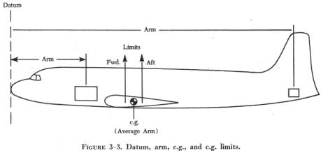
The Datum
The datum is an imaginary vertical plane from which all horizontal measurements are taken for balance purposes, with the aircraft in level flight attitude. It is a plane at right angles to the longitudinal axis of the aircraft. For each aircraft make and model, all locations of equipment, tanks, baggage compartments, seats, engines, propellers, etc., are listed in the Aircraft Specification or Type Certificate Data Sheets as being so many inches from the datum. There is no fixed rule for the location of the datum. In most cases it is located on the nose of the aircraft or some point on the aircraft structure itself. In a few cases, it is located a certain distance forward of the nose section of the aircraft. The manufacturer has the choice of locating the datum where it is most convenient for measurement, locating equipment, and weight and balance computation.
The datum location is indicated on most aircraft specifications. On some of the older aircraft, where the datum is not indicated, any convenient datum may be selected. However, once the datum is selected, it must be properly identified so that anyone who reads the figures will have no doubt about the exact datum location. Figure 3-2 shows some datum locations used by manufacturers.
The Arm
The arm is the horizontal distance that an item of equipment is located
from the datum. The arm's distance is always given or measured in inches,
and, except for a location which might be exactly on the datum (0), it
is preceded by the algebraic sign for plus (+) or minus (-). The plus (+)
sign indicates a distance aft of the datum and the minus (-) sign indicates
a distance forward of the datum.
| If the manufacturer chooses a datum that is at the most
forward location on an aircraft (or some distance forward of the aircraft),
all the arms will be plus (+) arms. Location of the datum at any other
point on the aircraft will result in some arms being plus (+), or aft of
the datum, and some arms minus (-), or forward of the datum.
The arm of each item is usually included in parentheses immediately after the item's name or weight in the specifications for the aircraft, e.g., seat (+23). When such information is not given, |
|
The Moment
A moment is the product of a weight multiplied by its arm. The moment of an item about the datum is obtained by multiplying the weight of the item by its horizontal distance from the datum. Likewise, the moment of an item about the CG can be computed by multiplying its weight by the horizontal distance from the CG.
A 20 pound weight located 30 inches from the datum would have a moment of 20 x 30 or 600 lb-in. Whether the value of 600 lb-in is preceded by a plus (+) or minus (-) sign depends on whether the moment is the result of a weight being removed or added and its location in relation to the datum.
Any item of weight added to the aircraft either side of the datum is plus weight. Any weight item removed is a minus weight. When multiplying a weight by an arm, the resulting moment is plus if the signs are alike and minus if the signs are unlike.
Center of Gravity
The CG of an aircraft is a point about which the nose heavy and tail heavy moments are exactly equal in magnitude. An aircraft suspended from this point would have no tendency to rotate in either a nose up or nose down attitude. It is the point about which the weight of an airplane or any object is concentrated.
Maximum Weight
The maximum weight is the maximum authorized weight of the aircraft and its contents, and is indicated in the specifications. For many aircraft there are variations to the maximum allowable weight, depending on the purpose and conditions under which the aircraft is to be flown. For example, a certain aircraft may be allowed a maximum gross weight of 2,750 pounds when flown in the normal category, but when flown in the utility category, the same aircraft's maximum allowable gross weight would be 2,175 pounds.
Empty Weight
The empty weight of an aircraft includes all operating equipment that has a fixed location and is actually installed in the aircraft. It includes the weight of the airframe, powerplant, required equipment, optional or special equipment, fixed ballast, hydraulic fluid, and residual fuel and oil.
Residual fuel and oil are the fluids that will not normally drain out because they are trapped in the fuel lines, oil lines, and tanks. They must be included in the aircraft's empty weight. Information regarding residual fluids in aircraft systems which must be included in the empty weight will be indicated in the Aircraft Specification.
Useful Load
The useful load of an aircraft is determined by subtracting the empty weight from the maximum allowable gross weight. For aircraft certificated in both the normal and utility categories, there may be two useful loads listed in the aircraft weight and balance records. An aircraft with an empty weight of 900 pounds will have a useful load of 850 pounds, if the normal category maximum weight is listed as 1,750 pounds. When the aircraft is operated in the utility category, the maximum gross weight may be reduced to 1,500 pounds, with a corresponding decrease in the useful load to 600 pounds. Some aircraft have the same useful load regardless of the category in which they are certificated.
The useful load consists of maximum oil, fuel, passengers, baggage, pilot, copilot, and crewmembers. A reduction in the weight of an item, where possible, may be necessary to remain within the maximum weight allowed for the category in which an aircraft is operating. Determining the distribution of these weights is called a weight check.
Empty Weight Center of Gravity
The empty weight CG, abbreviated EWCG, is the CG of an aircraft in its empty weight condition. It is an essential part of the weight and balance record of the aircraft.
It has no usefulness in itself, but serves as a basis for other computations and not as an indication of what the loaded CG will be. The EWCG is computed at the time of weighing, using formulas established for tailwheel and nosewheel type aircraft.
Empty Weight Center of Gravity Range
The EWCG range is an allowable variation of travel within the CG limits. When the EWCG of the aircraft falls within this range, it is impossible to exceed the EWCG limits using standard specification loading arrangements. Not all aircraft have this range indicated on the Aircraft Specifications or Type Certificate Data Sheets. Where it is indicated, the range is valid only as long as the aircraft is loaded according to the standard specification. The installation of items not listed in the specification will not permit use of this range.
Operating Center of Gravity Range
The operating CG range is the distance between the forward and rearward CG limits indicated in the pertinent Aircraft Specification or Type Certificate Data Sheets. These limits, determined at the time of design and manufacture, are the extreme loaded CG positions allowable within the applicable regulations controlling the design of the aircraft. These limits are shown in either percent of MAC (mean aerodynamic chord) or inches from the datum of the aircraft.
The loaded aircraft CG location must remain within these limits at all
times. Accordingly, detailed instructions for determining load distribution
are provided on placards, loading charts, and load adjusters.
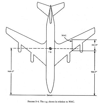
| Mean Aerodynamic Chord
The MAC is the mean average chord of the wing. An airfoil section is a cross section of a wing from leading edge to trailing edge. A chord is usually defined as an imaginary straight line drawn parallel to the airfoil through the leading and trailing edges of the section. The MAC of a constant chord wing would be the same as the actual chord of the wing. Any departure from a rectangular wing plan form will affect the length of the MAC and the resulting distance from the MAC leading edge to the aircraft wing leading edge. Figure 3-4 shows the MAC for a sweptwing aircraft. The aircraft CG is usually placed at the maximum forward position of the center of pressure on the MAC to obtain the desired stability. Because of the relationship between the CG location and the moments produced by aerodynamic forces, the greatest of which is lift, the CG location is generally expressed with respect to the wing. This is done by specifying CG in percent of the wing's MAC. |
 |
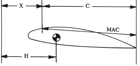
The location of the MAC, in relation to the datum, is given in the Aircraft Specifications or Type Certificate Data Sheets, the weight and balance report, or the aircraft flight manual. Compute the CG location in percent of MAC as follows:
|
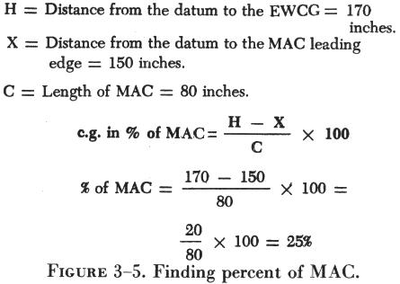
(1) Find the difference between the distance to the empty weight CG location from the datum and the distance to the leading edge of MAC from the datum. (2) Divide the difference by the length of the MAC. (3) Multiply the answer by 100. (4) The final answer is then expressed in percent. An example problem that utilizes the equation for computing percent of MAC is shown in figure 3-5. Aircraft Leveling Means Reference points are provided for leveling the aircraft on the ground. They are designated by the manufacturer and are indicated in the pertinent Aircraft Specifications. The most common leveling procedure is to place a spirit level at designated points on the aircraft structure. Some aircraft have special leveling scales built into the airframe structure. The scale is used with a plumb bob to level the aircraft longitudinally and laterally. |
 |
Weighing Points
In weighing an aircraft, the point on the scale at which the weight is concentrated is called the weighing point. When weighing light to medium weight land planes, the wheels are usually placed on the scales. This means that the weighing point is, in effect, the same location obtained by extending a vertical line through the center line of the axle and onto the scale.
Other structural locations capable of supporting the aircraft, such as jack pads on the main spar, may also be used if the aircraft weight is resting on the jack pads. The weighing points should be clearly indicated in the weight and balance report.
Zero Fuel Weight
The zero fuel weight is the maximum allowable weight of a loaded aircraft without fuel. Included in the zero fuel weight is the weight of cargo, passengers, and crew. All weights in excess of the zero fuel weight must consist of usable fuel.
Minimum Fuel
The term "minimum fuel" should not be interpreted to mean the minimum amount of fuel required to fly an aircraft. Minimum fuel, as it applies to weight and balance, is the amount of fuel that must be shown on the weight and balance report when the airplane is loaded for an extreme condition check.
The minimum fuel load for a small aircraft with a reciprocating engine for balance purposes is based on engine horsepower. It is calculated in the METO (maximum except takeoff) horsepower and is the figure used when the fuel load must be reduced to obtain the most critical loading on the CG limit being investigated. Either of 2 formulas may be used.
Formula 1:
Minimum fuel = 1/12 gallons per horsepower.
hp x 1/12 x 6 lb.
1200 x 1/12 x 6 = 1200 x 1/12 x 6 = 600 lb fuel.
Formula 2:
Minimum fuel = 1/2 lb per engine horsepower.
hp x 1/2 = minimum fuel.
1200 x 1/2 = 600 lb fuel.
This will be the minimum pounds of fuel required for the forward or rearward weight check.
For turbine engine powered aircraft, the minimum fuel load is specified by the aircraft manufacturer.
The fuel tank location in relation to the CG limit affected by the computation determines the use of minimum fuel. For example, when a forward weight check is performed, if the fuel tanks are located forward of the forward CG limit, they are assumed to be full. If they are located aft of the forward CG limit, they are assumed to be empty. If the minimum fuel required for a particular aircraft exceeds the capacity of the tanks located forward of the forward CG limit, the excess fuel must be loaded in the tanks that are aft of the forward CG limit. When a rearward weight check is conducted, the fuel loading conditions are opposite to those used for the forward check.
Full Oil
Full oil is the quantity of oil shown as oil capacity in the Aircraft Specifications. When weighing an aircraft, the oil tank may either contain the number of gallons of oil specified or be drained. When an aircraft with full oil tanks is weighed, the weight of the oil must be subtracted from the recorded readings to arrive at the actual empty weight. The weight and balance report must show whether weights include full oil or if the oil tanks were drained.
Tare Weight
Tare includes the weight of all extra items, such as jacks, blocks, and chocks on the weighing scale platform, except that of the item being weighed. The weight of these items, when included in the scale reading, is deducted to obtain the actual weight of the aircraft.