
The use of vacuum tubes in aircraft electrical and electronic systems is rapidly declining because of the many advantages of using transistors. On the other hand, some systems still employ vacuum tubes in special applications, and a large number of older model aircraft still in service are equipped with devices that use vacuum tubes. For these reasons a general study of vacuum tubes is still considered a necessary part of the aviation maintenance program.
Originally, vacuum tubes were developed for radio work. They are used in radio transmitters as amplifiers for controlling voltage and current, as oscillators for generating audio and radio frequency signals, and as rectifiers for converting alternating current into direct current. Radio tubes are used for similar purposes in many electrical devices in aircraft, such as the automatic pilot and the turbosupercharger regulator.
When a piece of metal is heated, the speed of the electrons in the metal is increased. If the metal is heated to a high enough temperature, the electrons are accelerated to the point where some of them actually leave the surface of the metal, as shown in figure 8-217. In a vacuum tube, electrons are supplied by a piece of metal, called a cathode, which is heated by an electric current. Within limits, the hotter the cathode the greater the number of electrons it will give off or emit.
To increase the number of electrons emitted, the cathode is usually coated with special chemical compounds. If the emitted electrons are not drawn away by an external field, they form about the cathode into a negatively charged cloud called the space charge. The accumulation of negative electrons near the emitter repels others coming from the emitter. The emitter, if insulated, becomes positive because of the loss of electrons. This establishes an electrostatic field between the cloud of negative electrons and the now positive cathode. A balance is reached when only enough electrons flow from the cathode to the area surrounding it to supply the loss caused by diffusion of the space charge.
Types of Vacuum Tubes
There are many different types of vacuum tubes, most of which fall into four general types: (1) The diode, (2) the triode, (3) the tetrode, and (4) the pentode. Of these, the diode is used almost exclusively for changing ac current to dc current. In some vacuum tubes, the cathode is heated by dc and is both the electron emitter and current carrying member, while in others the cathode is heated by ac. Tubes designed for ac operation employ a special heating element which heats the electron emitter (cathode) indirectly.
When a dc potential is applied between the cathode and another element in the tube called a plate, with the positive side of the voltage connected to the plate, the electrons emitted by the cathode are attracted to the plate. These two elements constitute the simplest form of vacuum tube, which is the diode. In the diode, electrons are attracted to the plate, when it is more positive than the cathode, and are repelled when the plate is less positive than the cathode.
Current flows through the tube when it is connected in a circuit only
when the plate is positive with respect to the cathode. Current does not
flow when the plate is negative (less positive) with respect to the cathode
as illustrated in figure 8-218. This characteristic
gives the diode its principle use, that of rectification, or the changing
of alternating current into direct current.
| Diode rectifiers are used in aircraft electrical systems,
especially when high voltage dc is desired for light loads. They may be
used as either halfwave or fullwave rectifiers; they may be used singly,
in parallel, or in bridge circuits. As shown in figure 8-219, a halfwave
rectifier contains two tube elements (plate and cathode). A fullwave rectifier
contains three elements (two plates and a cathode).
In the halfwave circuit, current flows only during the positive half of the cycle of the applied voltage (plate positive, cathode negative for electron flow). It flows from the cathode to the plate and then through the load back to the cathode. On the negative cycle of the applied voltage, no current flows through the tube. As a result, the rectified output voltage is dc, but it consists of pulses, or half cycles, of current. |
 |
In a vacuum tube connected as a fullwave rectifier, current flows to the load on both half cycles of the alternating voltage. In the fullwave rectifier, current flows from the top plate through the dc load on one alternation, and on the next alternation, current flows to the lower plate and through the load in the same direction.
Vacuum tube rectifiers have been replaced to a great degree in aircraft systems by dry disk or semiconductor diodes. In the study of solid state devices the process of rectification is treated in greater detail.
The triode tube is a three element tube. In addition to the plate and cathode, there is a third element, called the grid, located between the cathode and the plate as shown in figure 8-220. The grid is a fine wire mesh or screen. It serves to control the electron flow between the cathode and the plate. Whenever the grid is made more positive than the cathode, there is an increase in the number of electrons attracted to the plate, resulting in an increase in plate current flow. If the grid is made negative with respect to the cathode, electron movement to the plate is retarded and plate current flow decreases.
Usually the grid is negative with reference to the cathode. One method of making the grid negative is to use a small battery connected in series with the grid circuit. This negative voltage applied to the grid is called bias.
The most important use of a triode is as an amplifier tube. When a resistance
or impedance is connected in series in the plate circuit, the voltage drop
across it, which depends upon the current flowing through it, can be changed
by varying the grid voltage. A small change in grid voltage will cause
a large change in the voltage drop across the plate impedance. Thus, the
voltage applied to the grid is amplified in the plate circuit of the tube.
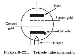
| A tetrode tube is a four element tube, the additional element
being the screen grid (figure 8-221). This grid is located between the
control grid and the plate. The screen grid is operated at a positive voltage
somewhat lower than the plate voltage. It reduces the sometimes undesirable
effect in tube operation caused by energy fed from the output of a tube
back into the input (grid) circuit.
Under certain operating conditions, this feedback action is very pronounced in a triode and causes the tube to act as an oscillator instead of an amplifier. The chief advantages of tetrodes over triodes are greater amplification for smaller input voltages, and less feedback from the plate to the grid circuit. |
 |
An undesirable characteristic of the tetrode tube is secondary emission.
Secondary emission is the term applied to the condition where electrons
are knocked out of the plate into the space between the elements of a tube
by rapidly moving electrons striking the plate. In triode tubes, since
the grid is negative with respect to the cathode, it repels the secondary
electrons and tube operation is undisturbed. In the tetrode, the effect
of secondary emission is especially noticeable since the screen grid, which
is positive with respect to the cathode, attracts the secondary electrons
and causes a reverse current to flow between the screen and plate.
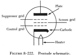 |
The effects of secondary emission are overcome by adding a third grid,
called the suppressor grid, between the screen grid and the plate. This
grid repels the secondary electrons toward the plate. A tube with three
grids is called a pentode, which has a high amplification factor and is
used to amplify weak signals. The schematic of a pentode is shown in figure
8-222.
Another type of vacuum tube is the gas tube. Gas filled tubes are primarily diodes and are used mostly as rectifiers. In tubes of this type the gas should be one ten-thousandth as dense as air under normal atmospheric pressure. When an electron meets a gas molecule, the energy imparted by the impact can cause the molecule (or atom) to lose or gain one or more electrons. Consequently, ionization takes place. |
Any gas or vapor having no ions is practically a perfect insulator. If two electrodes are placed in such a medium, no current will flow between them. However, gases always have some residual ionization because of cosmic rays, radioactive materials in the walls of the containers, or the action of light. If a potential is applied between two elements in such a gas, the ions migrate between them and give the effect of current flow. This is called the dark current because no visible light is associated with it.
If the voltage on the electrodes is increased, the current starts to rise. At a certain point, known as the threshold, the current suddenly begins to go up without any increase in applied voltage. If there is enough resistance in the external circuit to prevent the current from rising quickly, the voltage immediately drops to a lower value and breakdown occurs. This abrupt change takes place as a result of the ionization of the gas by electron collision.
The electrons released by the ionized gas join the stream and liberate other electrons. The process, then, is cumulative. Breakdown voltage is determined primarily by the type of gas, the materials used for the electrodes, and their size and spacing. Once ionization takes place, the current can rise to 50 milliamperes (ma.), or more, with little change in the voltage applied. If the voltage is increased, the current increases and the cathode is heated by the bombardment of the ions which strike it. When the tube gets hot enough, thermionic emission results.
This emission reduces the voltage loss in the tube, which, in turn, causes more current to flow and increases the rate of emission and ionization. This cumulative action causes a sudden decrease in the voltage drop across the tube and an extremely high rise in current flow. Unless the tube is designed to operate in this manner, it can be damaged by heavy current flow. This is basic to the formation of an arc; therefore, tubes that operate at these high currents are called arc tubes. For currents up to 50 milliamperes, the unit usually is small and is termed a glow tube because of the colored light it emits. An example of such a tube is the familiar neon light.
The principle of grid control can be applied to almost any gas tube,
but it is used specifically with cold cathode, hot cathode, and arc types
of triodes, and tetrodes. The hot cathode type of three element gas tube
is given the general name of thyratron.
| The phototube is another special type of vacuum tube. It
is basically the same as the simple diode discussed earlier. It has an
evacuated glass bulb, a cathode which emits electrons when light is allowed
to fall upon it, and a plate which attracts electrons when a voltage is
applied. The sensitivity of the tube depends on the frequency or color
of the light used to excite it and is specified in these terms.
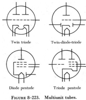
For example, some tubes are sensitive to red light, others to blue light. In most phototubes, the cathode resembles a half cylinder. It is covered with multiple layers of the rare metal, cesium, overlaid on cesium oxide, which, in turn, lies on a layer of silver. The plate is shaped like a small rod and is located in the center of the cathode. Other types of vacuum tubes include those with the characteristics of several tubes incorporated into one, as shown in figure 8-223. Among these, for example, are twin triode tubes containing two triode sections, in a single tube envelope, and diode-triode tubes with a rectifier diode and an amplifier triode in the same envelope. There are many other tube combinations. |
 |