FUELSYSTEMCONTAMINATION
FUEL SYSTEM CONTAMINATION
There are several forms of contamination in aviation fuel. The higher
the viscosity of the fuel, the greater is its ability to hold contaminants
in suspension. For this reason, jet fuels having a high viscosity are more
susceptible to contamination than aviation gasoline. The principal contaminants
that reduce the quality of both gasoline and turbine fuels are other petroleum
products, water, rust or scale, and dirt.
Water
Water can be present in the fuel in two forms: (1) Dissolved in the
fuel or (2) entrained or suspended in the fuel. Entrained water can be
detected with the naked eye. The finely divided droplets reflect light
and in high concentrations give the fuel a dull, hazy, or cloudy appearance.
Particles of entrained water may unite to form droplets of free water.
Fuel can be cloudy for a number of reasons. If the fuel is cloudy and the
cloud disappears at the bottom, air is present. If the cloud disappears
at the top, water is present. A cloud usually indicates a water in fuel
suspension. Free water can cause icing of the aircraft fuel system, usually
in the aircraft boost pump screens and low pressure filters. Fuel gauge
readings may become erratic because the water short circuits the aircraft's
electrical fuel cell quantity probe. Large amounts of water can cause engine
stoppage. If the free water is saline, it can cause corrosion of the fuel
system components.
Foreign Particles
Most foreign particles are found as sediment in the fuel. They are composed
of almost any material with which the fuel comes into contact. The most
common types are rust, sand, aluminum and magnesium compounds, brass shavings,
and rubber.
Rust is found in two forms: (1) Red rust, which is nonmagnetic and (2)
black rust, which is magnetic. They appear in the fuel as red or black
powder (which may resemble a dye), rouge, or grains. Sand or dust appears
in the fuel in a crystalline, granular, or glasslike form.
Aluminum or magnesium compounds appear in the fuel as a form of white
or gray powder or paste. This powder or paste becomes very sticky or gelatinous
when water is present. Brass is found in the fuel as bright gold colored
chips or dust. Rubber appears in the fuel as fairly large irregular bits.
All of these forms of contamination can cause sticking or malfunctions
of fuel metering devices, flow dividers, pumps, and nozzles.
Contamination with Other Types or Grades of Fuel
The unintentional mixing of petroleum products can result in fuels that
give unacceptable performance in the aircraft. An aircraft engine is designed
to operate most efficiently on fuel of definite specifications. The use
of fuels that differ from these specifications reduces operating efficiency
and can lead to complete engine failure.
Operators of turbine powered aircraft are sometimes forced by circumstances
to mix fuels. Such mixing, however, has very definite disadvantages. When
aviation gasoline is mixed with jet fuel, the TEL in the gasoline forms
deposits on the turbine blades and vanes. Continuous use of mixed fuels
may cause a loss in engine efficiency. However, on a limited usage basis,
they will have no detrimental effects on the engine.
Aviation gasoline containing by volume more than 0.5 percent of jet
fuel may be reduced below the allowable limits in knock rating. Gasoline
contaminated with turbine fuel is unsafe for use in reciprocating engines.
Microbial Growth
Microbial growth is produced by various forms of microorganisms that
live and multiply in the water interfaces of jet fuels. These organisms
may form a slime similar in appearance to the deposits found in stagnant
water. The color of this slime growth may be red, brown, gray, or black.
If not properly controlled by frequent removal of free water, the growth
of these organisms can become extensive. The organisms feed on the hydrocarbons
that are found in fuels, but they need free water in order to multiply.
Microorganisms have a tendency to mat, generally appearing as a brown
blanket which acts as a blotter to absorb more moisture. This mixture or
mat accelerates the growth of microorganisms. The buildup of microorganisms
not only can interfere with fuel flow and quantity indication, but, more
important, it can start electrolytic corrosive action.
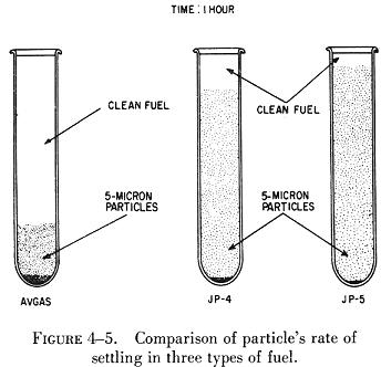
Sediment
Sediment appears as dust, powder, fibrous material, grains, flakes,
or stain. Specks or granules of sediment indicate particles in the visible
size range, i.e., approximately 40 microns or larger in size. (See figure
4-5.) The presence of any appreciable number of such particles indicates
either a malfunction of the filter/separators or a source of contamination
downstream of the filter/separator, or else an improperly cleaned sample
container. Even with the most efficient filter/separators and careful fuel
handling, an occasional visible particle will be encountered. These strays
are usually due to particle migration through the filter media and may
represent no particular problem to the engine or fuel control. The sediment
ordinarily encountered is an extremely fine powder, rouge, or silt. The
two principle components of this fine sediment are normally sand and rust.
Sediment includes both organic and inorganic matter. The presence of
appreciable quantities of fibrous materials (close to naked eye visibility)
is usually indicative of filter element breakdown, either because of a
ruptured element or mechanical disintegration of a component in the system.
Usually, high metal content of relatively large particles suggest a mechanical
failure somewhere in the system which is necessarily not limited to a metallic
filter failure. |
|
 |
In a clean sample of fuel, sediment should not be visible except upon
the most meticulous inspection. Persistent presence of sediment is suspect
and requires that appropriate surveillance tests and corrective measures
be applied to the fuel handling system.
Sediment or solid contamination can be separated into two categories:
(1) coarse sediment and (2) fine sediment.
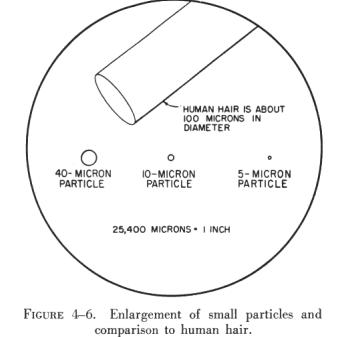
Course Sediment
Sediment that can be seen and that easily settles out of fuel or can
be removed by adequate filtration is coarse sediment. Ordinarily, particles
10 microns in size and larger are regarded as coarse sediment. (See figure
4-6.)
Coarse particles clog orifices and wedge in sliding valve clearances
and shoulders, causing malfunctions and excessive wear of fuel controls
and metering equipment. They are also effective in clogging nozzle screens
and other fine screens throughout the aircraft fuel system. |
Fine Sediment
Particles smaller than 10 microns may be defined as fine sediment. (See
figure 4-6.) Ninety eight percent of the fine sediment in fuel can be removed
by proper settling, filtration, and centrifuging. Particles in this range
accumulate throughout fuel controls, appearing as a dark shellac like surface
on sliding valves, and may also be centrifuged out in rotating chambers
as sludge like matter, causing sluggish operation of fuel metering equipment.
Fine particles are not visible to the naked eye as distinct or separate
particles; they will, however, scatter light and may appear as point flashes
of light or a slight haze in fuel.
Maximum possible settling time should be allowed in fuel tanks after
filling to allow reasonable settlement of water and sediment.
Contamination Detection
Coarse contamination can be detected visually. The major criterion for
contamination detection is that the fuel be clean, bright, and contain
no perceptible free water. Clean means the absence of any readily visible
sediment or entrained water. Bright refers to the shiny appearance of clean,
dry fuels. Free water is indicated by a cloud, haze, or a water slug. A
cloud may or may not be present when the fuel is saturated with water.
Perfectly clear fuel can contain as much as three times the volume of water
considered to be tolerable.
Several field methods for checking water content have been devised.
One is the adding of a food color that is soluble in water, but not in
fuel. Colorless fuel samples acquire a definite tint if water is present.
Another method uses a gray chemical powder that changes color to pink through
purple, if 30 or more p.p.m. (parts per million) of water are present in
a fuel sample. In a third method a hypodermic needle is used to draw a
fuel sample through a chemically treated filter. If the sample changes
the color of the filter from yellow to blue, the fuel contains at least
30 p.p.m. of water.
Since fuel drained from tank sumps may have been cold soaked, it should
be realized that no method of water detection can be accurate while the
fuel entrained water is frozen into ice crystals.
There is a good chance that water will not be drained or detected if
the sumps are drained while the fuel is below 32° F after being cooled
in flight. The reason for this is that the sump drains may not be at the
lowest point in the fuel tank while the airplane is in a flight attitude,
and water may accumulate and freeze on other areas of the tank where it
will remain undetected until it thaws.
Draining will be more effective if it is done after the fuel has been
undisturbed for a period of time during which the free water can precipitate
and settle to the drain point. The benefits of a settling period will be
lost, however, unless the accumulated water is removed from the drains
before the fuel is disturbed by internal pumps.
Contamination Control
The aircraft fuel system can be considered as being divided into three
parts when discussing clean fuel. The manufacturer produces clean fuel.
Contamination can occur at any time after the fuel is produced. The first
part of the fuel system is the delivery and storage system between the
refinery and the airport fuel service truck. Although this system is not
physically a part of the aircraft, it is of equal importance in controlling
contamination.
Anytime fuel is transferred it is susceptible to contamination. Therefore,
all aviation maintenance personnel should be familiar with the following
means of contamination control.
Fundamental in the control of contamination of turbine fuels are the
methods followed by the industry in receiving and storing any bulk shipment
of a petroleum product. These methods have long been established as sound,
and they are too well known to need repetition here. The refueling facilities
used by operators of turbine powered aircraft should incorporate the following
features:
1. Fuel being pumped into airport storage should pass through a filter
separator. The filter should meet the requirements of U.S. Government Specification
MIL-F-8508A.
2. Turbine fuels should be allowed to settle for a period of one hour
per foot of depth of the fuel before being withdrawn for use. This means
that ordinarily more than one storage tank must be provided for each grade
of product.
3. Storage tanks should be checked with litmus paper after each new
load of fuel is received and the fuel has settled. The litmus paper should
remain submerged for a minimum of 15 seconds. During periods of heavy rain
underground tanks should be checked with litmus paper more frequently.
4. Suction lines should be a minimum of 6 inches from the bottom of
the tank. Kerosene storage tanks should be equipped with floating type
suction lines. Floating suction does not remove the bottom product, which
may not have settled sufficiently. It also prevents reintroduction into
the fuel of any contamination at the bottom of the tank. Floating suction
is the only logical way to take full advantage of gravity in removing water
and particulate matter contamination. Its importance must not be minimized.
5. Fuel being withdrawn from storage should be passed through a filter
separator meeting the specification MIL-F-8508A.
6. Great care should be exercised in loading mobile fuelers to exclude
airborne dust and dirt, rain or other foreign material.
7. To lessen the likelihood of rust and scale the tanks of mobile fuelers
should be constructed of either stainless steel, nonferrous material or
steel coated with a reliable, inert material.
8. As turbine fuel is being dispensed into the aircraft from truck or
hydrant it should be filtered to a degree of 5 microns for solid particles
and contain no more than 0.0015 per cent of free and entrained water. Bypass
valves around the filter should not be permitted.
9. All the quality control procedures usually followed in handling aviation
gasoline should be employed. These include regular and frequent check of
filter separators; frequent quality check such as the "clear and bright"
test; and continual emphasis on cleanliness. Examples: "Don't let the hose
nozzle drag on the apron." "Keep the dust cap on the nozzle at all times
when nozzle is not in use."