 |
|
|
|
|||
It must be remembered, however, that even a straight wire has inductance, small though it may be when compared to that of a coil. AC motors, relays, and transformers contribute inductance to a circuit. Practically all ac circuits contain inductive elements. The symbol for inductance in formulas is the capital letter "L." Inductance is measured in henrys (abbreviated h). An inductor (coil) has an inductance of 1 henry if an e.m.f. of 1 volt is induced in the inductor when the current through the inductor is changing at the rate of 1 ampere per second. However, the henry is a large unit of inductance and is used with relatively large inductors having iron cores. The unit used for small air core inductors is the millihenry (mh). For still smaller air core inductors the unit of inductance is the microhenry (mh). Figure 8-172 shows a few of the various types of inductors, together with their symbols. |
|
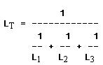
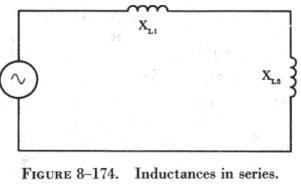
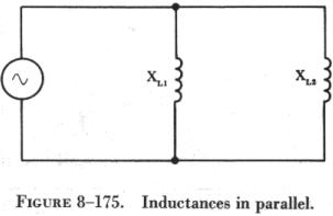
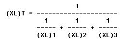
Inductors may be connected in a circuit in the same manner as resistors. When connected in series, the total inductance is the sum of the inductances of the inductors, or LT = L1 + L2 + L3, etc. When two or more inductors are connected in parallel, the total inductance is, like resistances in parallel, less than that of the smallest inductor, or
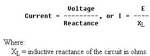
The total inductance of inductors connected in series-parallel can be computed by combining the parallel inductances and then adding the series values. In all cases, these formulas are valid, providing the magnetic fields of the inductors do not interact. Inductive Reactance The opposition to the flow of current which inductances put in a circuit is called inductive reactance. The symbol for inductive reactance is XL, and is measured in ohms, just as resistance is. In any circuit in which there is only resistance, the expression for the relationship of voltage and current is Ohm's law: I = E/R. Similarly, when there is inductance in an ac circuit, the relationship between voltage and current can be expressed as:
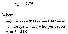
If all other circuit values remain constant, the greater the inductance in a coil, the greater the effect of self-induction, or opposition to the change in the value of current. As the frequency increases, the inductive reactance increases, since the greater the rate of current change the more the opposition to change by the coil increases. Therefore, inductive reactance is proportional to inductance and frequency or,
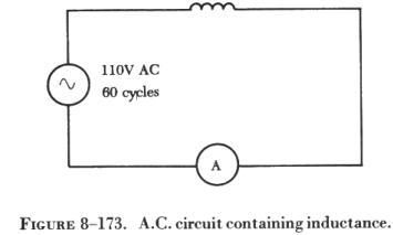
Solution: To find the inductive reactance:
|
|||||||||
| ©AvStop Online Magazine Contact Us Return to Airframe & Powerplant General Handbook |