The rules and equations for dc circuits apply to ac circuits only when the circuits contain resistance alone, as in the case of lamps and heating elements. In order to use effective values of voltage and current in ac circuits, the effect of inductance and capacitance with resistance must be considered.
The combined effect of resistance, inductive reactance, and capacitive reactance makes up the total opposition to current flow in an ac circuit. This total opposition is called impedance and is represented by the letter "Z." The unit for the measurement of impedance is the ohm.
Series AC Circuits
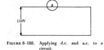
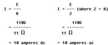
| If an ac circuit consists of resistance only, the value of the impedance is the same as the resistance, and Ohm's law for an ac circuit, I = E/Z, is exactly the same as for a dc circuit. In figure 8-188 a series circuit containing a lamp with 11 ohms resistance connected across a source is illustrated. To find how much current will flow if 110 volts dc are applied and how much current will flow if 110 volts ac are applied, the following examples are solved: | |
|
| When ac circuits contain resistance and either inductance
or capacitance, the impedance, Z, is not the same as the resistance, R.
The impedance of a circuit is the circuit's total opposition to the flow
of current. In an ac circuit, this opposition consists of resistance and
reactance, either inductive or capacitive, or elements of both.
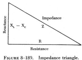
Resistance and reactance cannot be added directly, but they can be considered as two forces acting at right angles to each other. Thus, the relation between resistance, reactance, and impedance may be illustrated by a right triangle, as shown in figure 8-189. |
 |
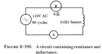 |
Since these quantities may be related to the sides of a right triangle, the formula for finding the impedance, or total opposition to current flow in an ac circuit, can be found by using the law of right triangles. This theorem, called the Pythagorean theorem, applies to any right triangle. It states that the square of the hypotenuse is equal to the sum of the squares of the other two sides. Thus, the value of any side of a right triangle can be found if the other two sides are known. If an ac circuit contains resistance and inductance, as shown in figure 8-190, the relation between the sides can be stated as: |
This formula can be used to determine the impedance when the values of inductive reactance and resistance are known. It can be modified to solve for impedance in circuits containing capacitive reactance and resistance by substituting XC in the formula in place of XL. In circuits containing resistance with both inductive and capacitive reactance, the reactances can be combined, but because their effects in the circuit are exactly opposite, they are combined by subtraction: X = XL - XC or X = XC - XL (the smaller number is always subtracted from the larger). In figure 8-190, a series circuit consisting of resistance and inductance connected in series is connected to a source of 110 volts at 60 cycles per second. The resistive element is a lamp with 6 ohms resistance, and the inductive element is a coil with an inductance of 0.021 henry. What is the value of the impedance and the current through the lamp and the coil?
Solution:
First, the inductive reactance of the coil is computed:
XL = 2 p x f x L
XL = 6.28 x 60 x 0.021
XL = 8 ohms inductive reactance.
Next, the total impedance is computed:
Z = the square root of R2 + XL2
Z = the square root of 62 + 82
Z = the square root of 36 + 64
Z = the square root of 100
Z = 10 ohms impedance.
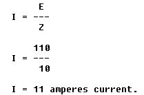
Then the current flow,
The voltage drop across the resistance (ER) is
ER = I x R
ER = 11 x 6 = 66 volts.
The voltage drop across the inductance (EXL) is
EXL = I x XL
EXL = 11 x 8 = 88 volts.
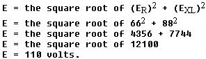
The sum of the two voltages is greater than the impressed voltage. This
results from the fact that the two voltages are out of phase and, as such,
represent the maximum voltage. If the voltage in the circuit is measured
by a voltmeter, it will be approximately 110 volts, the impressed voltage.
This can be proved by the equation
In figure 8-191, a series circuit is illustrated in which a capacitor of 200 mf is connected in series with a 10 ohm lamp. What is the value of the impedance, the current flow, and the voltage drop across the lamp? |
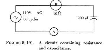 |
Solution:
First the capacitance is changed from microfarads to farads. Since 1
million microfarads equal 1 farad, then
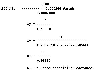
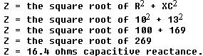
To find the impedance,
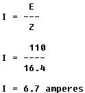
To find the current,
The voltage drop across the lamp (ER) is
ER = 6.7 x 10
ER = 67 volts
The voltage drop across the capacitor (EXC) is
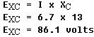
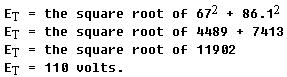
The sum of these two voltages does not equal the applied voltage, since the current leads the voltage. To find the applied voltage, the formula ET = the square root of (ER)2 + (EXC)2 is used.
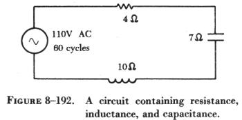
When the circuit contains resistance, inductance, and capacitance, the equation
Z = the square root of R2 + (XL - XC)2
is used to find the impedance.
Example:
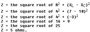
What is the impedance of a series circuit (figure 8-192), consisting of a capacitor with a reactance of 7 ohms, an inductor with a reactance of 10 ohms, and a resistor with a resistance of 4 ohms?
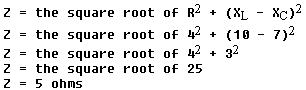
Assuming that the reactance of the capacitor is 10 ohms and the reactance of the inductor is 7 ohms, then XC is greater than XL. Thus,
Parallel AC Circuits
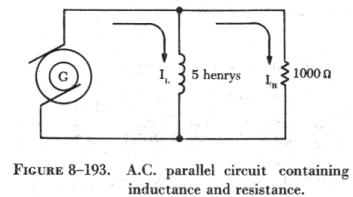
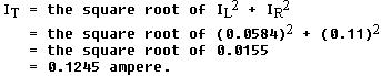
| The methods used in solving parallel ac circuit problems are basically the same as those used for series ac circuits. Out of phase voltages and currents can be added by using the law of right triangles, but in solving circuit problems, the currents through the branches are added, since the voltage drops across the various branches are the same and are equal to the applied voltage. In figure 8-193, a parallel ac circuit containing an inductance and a resistance is shown schematically. The current flowing through the inductance, IL, is 0.0584 ampere, and the current flowing through the resistance is 0.11 ampere. What is the total current in the circuit? |
 |
Solution:
Since inductive reactance causes voltage to lead the current, the total current, which contains a component of inductive current, lags the applied voltage. If the current and voltages are plotted, the angle between the two, called the phase angle, illustrates the amount the current lags the voltage.
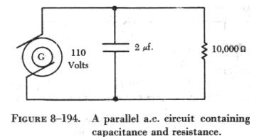
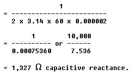
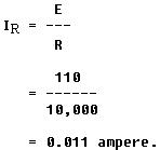
In figure 8-194, a 110 volt generator is connected to a load consisting
of a 2 ![]() capacitance and
a 10,000 ohm resistance in parallel. What is the value of the impedance
and total current flow?
capacitance and
a 10,000 ohm resistance in parallel. What is the value of the impedance
and total current flow?
Solution:
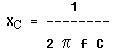
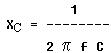
First, find the capacitive reactance of the circuit:
Changing 2![]() to farads and
entering the values into the formula given:
to farads and
entering the values into the formula given:
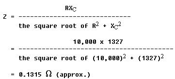
To find the impedance, the impedance formula used in a series ac circuit must be modified to fit the parallel circuit:
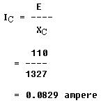
To find the current through the capacitance:
To find the current flowing through the resistance:
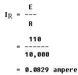
To find the current flowing through the resistance:
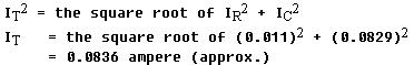
To find the total current in the circuit:
Resonance
It has been shown that both inductive reactance (XL = 2![]() f L) and capacitive reactance
f L) and capacitive reactance
are functions of an alternating current frequency. Decreasing the frequency decreases the ohmic value of the inductive reactance, but a decrease in frequency increases the capacitive reactance. At some particular frequency, known as the resonant frequency, the reactive effects of a capacitor and an inductor will be equal. Since these effects are the opposite of one another, they will cancel, leaving only the ohmic value of the resistance to oppose current flow in a circuit. If the value of resistance is small or consists only of the resistance in the conductors, the value of current flow can become very high.
In a circuit where the inductor and capacitor are in series, and the frequency is the resonant frequency, or frequency of resonance, the circuit is said to be "in resonance" and is referred to as a series resonant circuit. The symbol for resonant frequency is Fn.
If, at the frequency of resonance, the inductive reactance is equal to the capacitive reactance, then
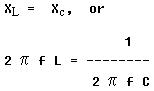
Dividing both sides by 2 fL,
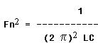
Extracting the square root of both sides gives
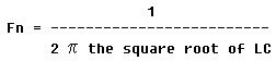
Where Fn is the resonant frequency in cycles per second, C is the capacitance in farads, and L is the inductance in henrys. With this formula the frequency at which a capacitor and inductor will be resonant can be determined.
To find the inductive reactance of a circuit use
![]()
The impedance formula used in a series ac circuit must be modified to fit a parallel circuit.
![]()
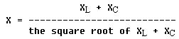
To find the parallel networks of inductance and capacitive reactors use
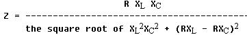
To find the parallel networks with resistance capacitive and inductance use:
Since at the resonant frequency XL cancels XC, the current can become
very large, depending on the amount of resistance. In such cases, the voltage
drop across the inductor or capacitor will often be higher than the applied
voltage.
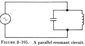
| In a parallel resonant circuit (figure 8-195), the reactances
are equal and equal currents will flow through the coil and the capacitor.
Since the inductive reactance causes the current through the coil to lag the voltage by 90°, and the capacitive reactance causes the current through the capacitor to lead the voltage by 90°, the two currents are 180° out of phase. The canceling effect of such currents would mean that no current would flow from the generator and the parallel combination of the inductor and the capacitor would appear as an infinite impedance. In practice, no such circuit is possible, since some value of resistance is always present, and the parallel circuit, sometimes called a tank circuit, acts as a very high impedance. It is also called an antiresonant circuit, since its effect in a circuit is opposite to that of a series resonant circuit, in which the impedance is very low. |
 |
| Power in AC Circuits
In a dc circuit, power is obtained by the equation, P = EI, (watts equal volts times amperes). Thus, if 1 ampere of current flows in a circuit at a pressure of 200 volts, the power is 200 watts. The product of the volts and the amperes is the true power in the circuit. In an ac circuit, a voltmeter indicates the effective voltage and an ammeter indicates the effective current. The product of these two readings is called the apparent power. Only when the ac circuit is made up of pure resistance is the apparent power equal to the true power (figure 8-196). |
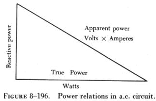 |
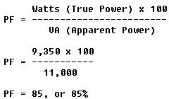
When there is capacitance or inductance in the circuit, the current and voltage are not exactly in phase, and the true power is less than the apparent power. The true power is obtained by a wattmeter reading. The ratio of the true power to the apparent power is called the power factor and is usually expressed in percent. In equation form, the relationship is:
![]()
Problem:
A 220 volt ac motor takes 50 amperes from the line, but a wattmeter in the line shows that only 9,350 watts are taken by the motor. What is the apparent power and the power factor?
Solution: