The requirements for a series-parallel circuit are as follows:
(1) power source (battery).
(2) conductors (wires).
(3) load (resistances).
(4) more than one path for current flow.
(5) a control (switch).
(6) safety device (fuse).
|
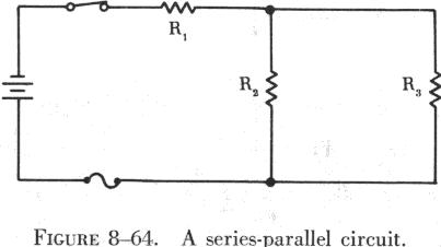
Most circuits in electrical equipment are not series or parallel circuits.
They are usually series-parallel circuits, which are combinations of series
and parallel circuits. A series-parallel circuit consists of groups of
parallel resistors connected in series with other resistors. An example
of a series-parallel circuit is shown in figure 8-64.
The requirements for a series-parallel circuit are as follows: (1) power source (battery).
|
| While series-parallel circuits may appear extremely complex,
the same rule used for series and parallel circuits can be applied to simplify
and solve them.
The easiest method of handling series-parallel circuits is to break them apart and redraw them as equivalent circuits. The circuit in figure 8-65 is an example of a simple series-parallel circuit that can be redrawn to illustrate this procedure. In this circuit the same voltage is applied to R2 and R3; thus they are in parallel. The equivalent resistance of these two resistors is equal to the value of one resistor divided by the number of resistors in parallel. This is true only when the parallel resistors have the same ohmic value. If this rule is applied, the circuit can be redrawn as shown in figure 8-66. |
 |
This has converted the original series-parallel circuit into a simple
series circuit containing two resistances. To further simplify the circuit,
the two series resistances can be added, and the circuit can be redrawn
as shown in figure 8-67.
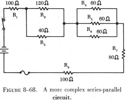
| Although the last redrawing of the circuit could have been
omitted and the calculations done mentally, this circuit illustrates clearly
that one 25 ohm resistor is the resistive equivalent of the three resistors
of the original circuit. Figure 8-68 contains a more complex series-parallel
circuit.
The first step in simplifying this circuit is to reduce each group of parallel resistors to a single equivalent resistor. The first group is the parallel combination of R2 and R3. Since these resistors have unequal values of resistance, the formula for two parallel resistances is used:
|
 |
Then the parallel combination of ![]() W
resistor, as shown in figure 8-69.
W
resistor, as shown in figure 8-69.
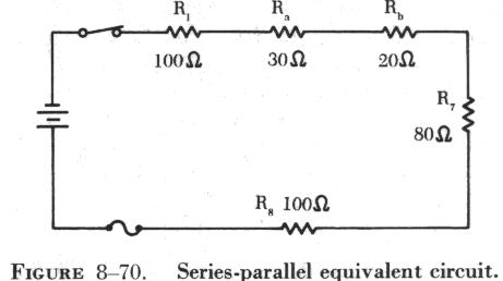
| Next, the equivalent resistance of the parallel combination
of
The parallel combination of R4, R5, and R6 can now be redrawn as a single 20 ohm resistor, as shown in figure 8-70. The original series-parallel circuit has now been replaced with its equivalent series circuit. This circuit could be redrawn again to replace the five resistors in series with one 330 ohm resistor. |
 |
This can be proved by using the total resistance formula for series circuits:
![]()
The first series-parallel circuit used is redrawn to discuss the behavior
of current flow (figure 8-71).
 |
Unlike the parallel circuit, the branch currents, I1 and I2, cannot
be established using the applied voltage. Since R1 is in series with the
parallel combination of R2 and R3, a portion of the applied voltage is
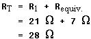
dropped across R1. In order to find the branch currents, total resistance
and total current must be found first. Since R2 and R3 are equal resistance,
|
Total resistance is
Using Ohm's law, total current is
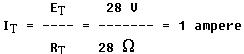
| The total current, 1 ampere, flows through R1 and divides
at point A, with part of the current flowing through R2, and the other
part through R3. Since R2 and R3 are of equal size, it is obvious that
half of the total current, or 0.5 amps, will flow through each branch.
The voltage drops in the circuit are determined by Ohm's law: The voltage drops across parallel resistors are always equal. It should also be remembered that, when the voltage is held constant and the resistance of any resistor in a series-parallel circuit is increased, the total current will decrease. This should not be confused as adding another parallel resistor to a parallel combination, which could reduce total resistance and increase total current flow. |
 |