TYPESOFDC
TYPES OF DC GENERATORS
| There are three types of dc generators: series wound, shunt
wound, and shunt series or compound wound. The difference in type depends
on the relationship of the field winding to the external circuit.
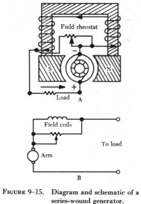
Series Wound DC Generators
The field winding of a series generator is connected in series with
the external circuit, called the load (figure 9-15). The field coils are
composed of a few turns of large wire; the magnetic field strength depends
more on the current flow rather than the number of turns in the coil. Series
generators have very poor voltage regulation under changing load, since
the greater the current through the field coils to the external circuit,
the greater the induced e.m.f. and the greater the terminal or output voltage.
Therefore, when the load is increased, the voltage increases; likewise,
when the load is decreased, the voltage decreases. The output voltage of
a series wound generator may be controlled by a rheostat in parallel with
the field windings, as shown in A of figure 9-15. Since the series wound
generator has such poor regulation, it is never employed as an airplane
generator. Generators in airplanes have field windings which are connected
either in shunt or in compound. |
|
Shunt Wound DC Generators
A generator having a field winding connected in parallel with the external
circuit is called a shunt generator, as shown in A and B of figure
9-16. The field coils of a shunt generator contain many turns of small
wire; the magnetic strength is derived from the large number of turns rather
than the current strength through the coils. If a constant voltage is desired,
the shunt wound generator is not suitable for rapidly fluctuating loads.
Any increase in load causes a decrease in the terminal or output voltage,
and any decrease in load causes an increase in terminal voltage; since
the armature and the load are connected in series, all current flowing
in the external circuit passes through the armature winding. Because of
the resistance in the armature winding, there is a voltage drop (IR drop
= current x resistance). As the load increases, the armature current increases
and the IR drop in the armature increases. The voltage delivered to the
terminals is the difference between the induced voltage and the voltage
drop; therefore, there is a decrease in terminal voltage. This decrease
in voltage causes a decrease in field strength, because the current in
the field coils decreases in proportion to the decrease in terminal voltage;
with a weaker field, the voltage is further decreased.
When the load decreases, the output voltage increases accordingly, and
a larger current flows in the windings. This action is cumulative, so the
output voltage continues to rise to a point called field saturation, after
which there is no further increase in output voltage.
The terminal voltage of a shunt generator can be controlled by means
of a rheostat inserted in series with the field windings as shown in A
of figure 9-16. As the resistance is increased,
the field current is reduced; consequently, the generated voltage is reduced
also. For a given setting of the field rheostat, the terminal voltage at
the armature brushes will be approximately equal to the generated voltage
minus the IR drop produced by the load current in the armature; thus, the
voltage at the terminals of the generator will drop as the load is applied.
Certain voltage sensitive devices are available which automatically adjust
the field rheostat to compensate for variations in load. When these devices
are used, the terminal voltage remains essentially constant.
Compound Wound DC Generators
A compound wound generator combines a series winding and a shunt winding
in such a way that the characteristics of each are used to advantage. The
series field coils are made of a relatively small number of turns of large
copper conductor, either circular or rectangular in cross section, and
are connected in series with the armature circuit. These coils are mounted
on the same poles on which the shunt field coils are mounted and, therefore,
contribute a magnetomotive force which influences the main field flux of
the generator. a diagrammatic and a schematic illustration of a compound
wound generator is shown in A and B of figure 9-17.
If the ampere turns of the series field act in the same direction as
those of the shunt field, the combined magnetomotive force is equal to
the sum of the series and shunt field components. Load is added to a compound
generator in the same manner in which load is added to a shunt generator,
by increasing the number of parallel paths across the generator terminals.
Thus, the decrease in total load resistance with added load is accompanied
by an increase in armature circuit and series field circuit current.
The effect of the additive series field is that of increased field flux
with increased load. The extent of the increased field flux depends on
the degree of saturation of the field as determined by the shunt field
current. Thus, the terminal voltage of the generator may increase or decrease
with load, depending on the influence of the series field coils. This influence
is referred to as the degree of compounding.
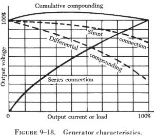
A flat compound generator is one in which the no load and full load
voltages have the same value; whereas an under compound generator has a
full load voltage less than the no load value, and an over compound generator
has a full load voltage which is higher than the no load value. Changes
in terminal voltage with increasing load depends upon the degree of compounding.
If the series field aids the shunt field, the generator is said to be
cumulative compounded (B of figure 9-17).
If the series field opposes the shunt field, the machine is said to
be differentially compounded, or is called a differential generator.
Compound generators are usually designed to be overcompounded. This
feature permits varied degrees of compounding by connecting a variable
shunt across the series field. Such a shunt is sometimes called a diverter.
Compound generators are used where voltage regulation is of prime importance.
| Differential generators have somewhat the same characteristics
as series generators in that they are essentially constant current generators.
However, they generate rated voltage at no load, the voltage dropping materially
as the load current increases. Constant current generators are ideally
suited as power sources for electric arc welders and are used almost universally
in electric arc welding.
If the shunt field of a compound generator is connected across both
the armature and the series field, it is known as a long shunt connection,
but if the shunt field is connected across the armature alone, it is called
a short shunt connection. These connections produce essentially the same
generator characteristics.
A summary of the characteristics of the various types of generators
discussed is shown graphically in figure 9-18. |
|
Three Wire Generators
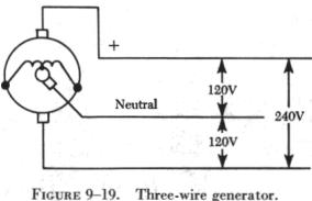 |
Some dc generators, called three wire generators, are designed to deliver
240 volts, or 120 volts from either side of a neutral wire (figure 9-19).
This is accomplished by connecting a reactance coil to opposite sides of
the commutator, with the neutral connected to the midpoint of the reactance
coil. Such a reactance coil acts as a low loss voltage divider. If resistors
were used, the IR loss would be prohibitive unless the two loads were perfectly
matched. The coil is built into some generators as part of the armature,
with the midpoint connected to a single slip ring which the neutral contacts
by means of a brush. In other generators, the two connections to the commutator
are connected, in turn, to two slip rings, and the reactor is located outside
the generator. |
In either case, the load unbalance on either side of the neutral must
not be more than 25 percent of the rated current output of the generator.
The three wire generator permits simultaneous operation of 120 volt lighting
circuits and 240 volt motors from the same generator.
Armature Reaction
Current flowing through the armature sets up electromagnetic fields
in the windings. These new fields tend to distort or bend the magnetic
flux between the poles of the generator from a straight line path. Since
armature current increases with load, the distortion becomes greater with
an increase in load. This distortion of the magnetic field is called armature
reaction and is illustrated in figure 9-20.
Armature windings of a generator are spaced in such a way that, during
rotation of the armature, there are certain positions when the brushes
contact two adjacent segments, thereby shorting the armature windings to
these segments. Usually, when the magnetic field is not distorted, there
is no voltage being induced in the shorted windings, and, therefore, no
harmful results occur from the shorting of the windings. However, when
the field is distorted, a voltage is induced in these shorted windings
and sparking takes place between the brushes and the commutator segments.
Consequently, the commutator becomes pitted, the wear on the brushes becomes
excessive, and the output of the generator is reduced. To correct this
condition, the brushes are set so that the plane of the coils which are
shorted by the brushes is perpendicular to the distorted magnetic field,
which is accomplished by moving the brushes forward in the direction of
rotation. This operation is called shifting the brushes to the neutral
plane, or plane of commutation. The neutral plane is the position where
the plane of the two opposite coils is perpendicular to the magnetic field
in the generator. On a few generators, the brushes can be shifted manually
ahead of the normal neutral plane to the neutral plane caused by field
distortion. On nonadjustable brush generators, the manufacturer sets the
brushes for minimum sparking.
Interpoles may be used to counteract some of the effects of field distortion,
since shifting the brushes is inconvenient and unsatisfactory, especially
when the speed and load of the generator are changing constantly. An interpole
is a pole placed between the main poles of a generator. For example, a
four pole generator has four interpoles, which are north and south poles,
alternately, as are the main poles. A four pole generator with interpoles
is shown in figure 9-21.
An interpole has the same polarity as the next main pole in the direction
of rotation. The magnetic flux produced by an interpole causes the current
in the armature to change direction as an armature winding passes under
it. This cancels the electromagnetic fields about the armature windings.
The magnetic strength of the interpoles varies with the load on the generator;
and since field distortion varies with the load, the magnetic field of
the interpoles counteracts the effects of the field set up around the armature
windings and minimizes field distortion. Thus, the interpole tends to keep
the neutral plane in the same position for all loads on the generator;
therefore, field distortion is reduced by the interpoles, and the efficiency,
output, and service life of the brushes are improved.
Generator Ratings
A generator is rated in power output. Since a generator is designed
to operate at a specified voltage, the rating usually is given as the number
of amperes the generator can safely supply at its rated voltage.
Generator rating and performance data are stamped on the name plate
attached to the generator. When replacing a generator, it is important
to choose one of the proper rating.
The rotation of generators is termed either clockwise or counterclockwise,
as viewed from the driven end. Usually, the direction of rotation is stamped
on the data plate. If no direction is stamped on the plate, the rotation
may be marked by an arrow on the cover plate of the brush housing. It is
important that a generator with the correct direction of rotation be used;
otherwise the voltage will be reversed.
| The speed of an aircraft engine varies from idle rpm to
takeoff rpm; however, during the major portion of a flight, it is at a
constant cruising speed. The generator drive is usually geared to revolve
the generator between 1 1/8 and 1 1/2 times the engine crankshaft speed.
Most aircraft generators have a speed at which they begin to produce their
normal voltage. Termed the "coming in" speed, it is usually about 1,500
rpm.
Generator Terminals
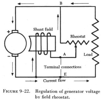
On most large 24 volt generators, electrical connections are made to
terminals marked B, A, and E. (See figure 9-22.) The positive armature
lead in the generator connects to the B terminal. The negative armature
lead connects to the E terminal. The positive end of the shunt field winding
connects to terminal A, and the opposite end connects to the negative terminal
brush. Terminal A receives current from the negative generator brush through
the shunt field winding. This current passes through the voltage regulator
and back to the armature through the positive brush. Load current, which
leaves the armature through the negative brushes, comes out of the E lead
and passes through the load before returning to the armature through the
positive brushes. |
|