Many airplanes are equipped with ADF (Automatic Direction Finder) radios which operate in the low and medium frequency bands (Fig. 12-9). By tuning to low frequency (LF) radio stations such as nondirectional radiobeacons (NDB), or to commercial broadcast (AM) stations, a pilot may use ADF for navigation in cross-country flying. NDB frequency and identification information may be obtained from aeronautical charts and the Airport/Facility Directory. Some major commercial broadcast station locations and frequencies are shown on sectional aeronautical charts. Positive station identification is essential when navigating with the ADF. The Morse codes are used to identify the NDB stations while the commercial broadcast stations are identified at random times by the station's announcer.

Most ADF radio receivers signals are in the frequency spectrum of 190 kHz to 1750 kHz, which includes LF and MF navigation facilities, and the AM commercial broadcast stations. Primarily for air navigation, the LF/MF stations are FAA and privately operated nondirectional radiobeacons. Some broadcast stations operate only during daylight hours, and many of the low powered stations transmit on identical frequencies and may cause erratic ADF indications.
The ADF has automatic direction seeking qualities which result in the bearing indicator always pointing to the station to which it is tuned. That is, when the bearing pointer is on the nose position, the station is directly ahead of the airplane; when the pointer is on the tail position, the station is directly behind the airplane; and when the pointer is 90 degrees to either side (wingtip position), the station is directly off the respective wingtip.

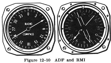
The more commonly used ADF instrument has a stationary azimuth dial graduated from 0 degrees up to 360 degrees (with 0 degrees at the top of the instrument to represent the airplane's nose). In this type, the bearing pointer shows only the station's relative bearing, i.e., the angle from the nose of the airplane to the station (Fig. 12-10). A more sophisticated instrument called a Radio Magnetic Indicator (RMI) uses a 360 degree azimuth dial which, being slaved to a gyro compass, rotates as the airplane turns and continually shows the Magnetic Heading at the top of the instrument. Thus, with this rotating azimuth referenced to a magnetic direction, the bearing pointer superimposed on the azimuth indicates the Magnetic Bearing to the station.
The easiest, and perhaps the most common method of using ADF, is to "home" to the station. Since the ADF pointer always points to the station, the pilot can simply head the airplane so that the pointer is on the 0 degree or nose position. The station, then will be directly ahead of the airplane. With a crosswind, however, the airplane would continually drift to the side and, unless a corrective change in heading is made, would no longer be flying straight to the station. This would be indicated by the pointer moving to the upwind side of the nose position on the dial. By periodically turning the airplane into the wind (toward the head of the pointer) so as to continually return the pointer to the 0 degree position, the airplane can be flown to the station, although in a curving flightpath as a result of wind drift. The lighter the crosswind and the shorter the distance from the station, the less the flightpath curves. Upon arrival at and passing the station, the pointer will swing 180 degrees from a nose position to a tail position.
ADF should be considered as a moving, "fluid" thing. The number to which the bearing indicator points on the fixed azimuth dial has no directional meaning to the pilot until it is related to the airplane's heading. To apply this relationship, the magnetic heading must be observed carefully when reading the Relative Bearing to the station. Any time the airplane's heading is changed, the Relative Bearing will be changed an equal number of degrees.
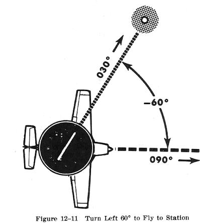
To determine the Magnetic Bearing to a station on a fixed ADF azimuth dial, the pilot may imagine the airplane as being in the center of the fixed azimuth, with the nose of the airplane at the 0 degree position, the tail at the 180 degree position, and the left and right wingtips at the 270 degree and 090 degree positions, respectively. When the pointer is on the nose position, the airplane is heading straight to the station and the Magnetic Bearing can be read directly from the magnetic compass. If the pointer is left or right of the nose, the pilot should note the direction and number of degrees of turn that would (if the airplane were to be headed to that station) move the pointer to the nose position, and mentally apply this to the airplane's heading. For example, in Fig. 12-11, when the airplane is headed 090 degrees, the pointer is 60 degrees to the left of the nose position. A turn 60 degrees to the left would place the pointer on the nose position. If the airplane were to be turned 60 degrees to the left, the heading would be 030 degrees. The bearing from the station is the reciprocal - or 210 degrees.

One of the several valuable uses of ADF is the determination of the airplane's position along the course being flown. Even though the airplane is following a course along a VOR radial, obtaining an ADF bearing that crosses the course will establish a "fix" or position along that course. This is particularly advantageous when an off course VOR is not available for a cross bearing or when the only VOR receiver must be used as the primary tracking system.