
![]()
|
|
||
| CHAPTER 3. Components and Systems
Fuel System Components The WSC aircraft is equipped with fuel tanks usually ranging in capacity from 5 to 20 gallons. As with any aircraft, knowing how much fuel the tank holds is crucial to fl ight operations. The LSA defi nition has no limitations on the size of the fuel tank, unlike its ultralight vehicle predecessor. Generally, the fuel tank is located close to the CG, so fuel burn does not affect the balance of the carriage. Some fuel tanks are clear for visual inspection of the amount of fuel on board [Figure 3-50], while others have tanks that are not visible and require fuel level probes for instrument panel indication of fuel. [Figure 3-51] 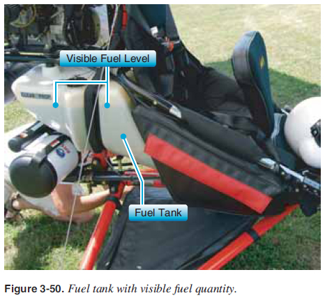 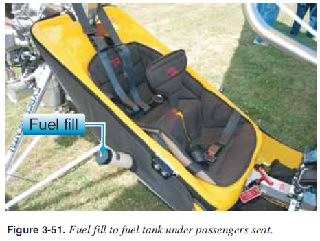 Fuel lines exit the fuel tank, and may incorporate a primer bulb, fuel fi lters, fuel pump, and/or a primer system, all of which must be integrated into the carriage. A fuel venting system is also required, which can be a hole in the fuel fi ller or lines running to vent at an appropriate location. A fuel shut-off valve may be installed and can be located anywhere in the fuel line. Some designs have a fuel tank sump drain valve to remove water and solid contaminants. Engine and Gearbox The typical WSC aircraft engine can be two or four stroke, liquid or air cooled, and normally ranges from 50 to 100 horsepower. Some engines have electric starters and some have pull starters. Most WSC aircraft engines have reduction drives that, when attached, reduce the propeller rpm from ½ to ¼ the engine rpm. [Figure 3-52] 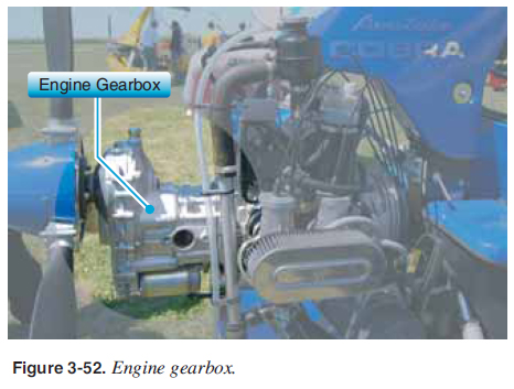 A signifi cant amount of the total aircraft empty weight is determined by the powerplant (engine, gearbox, and propeller) and mounting confi guration. When trailering the WSC aircraft over bumpy terrain or over long trips, the bouncing of the carriage in the trailer can put extreme stress on this mounting system. In addition, repeated hard landings of the carriage can also stress the welds of the engine mount. Consistent detailed inspections of the engine mount should be an important part of every prefl ight and postfl ight inspection. The powerplant systems are as varied as the WSC aircraft they power. Modern technology has allowed these systems to become lighter, quieter, more efficient, and, most importantly, dependable. The Propeller Propellers are “power converters” that change the engine horsepower into thrust. Thrust is the force that propels the aircraft through the air by pushing the WSC aircraft forward. Aerodynamically speaking, a propeller is a rotating airfoil and the same principles that apply to the wing applies to the propeller, except the propeller provides a horizontal force of thrust. Propellers typically consist of two, three, or four blades. [Figures 3-53 and 3-54] Propellers can be ground adjustable or fi xed pitch. Variable pitch fl ight propellers are not allowed on LSA. The pitch should be properly set for your WSC aircraft to provide the recommended rpm of the engine at full power. The POH should be consulted if there is any question about the propeller rpm and adjusting or replacing the propeller. Propellers are specifi cally matched to the engine power, gear reduction and speed range of the aircraft. Therefore, not just any propeller may be put on any engine. The POH requires specifi c propellers that are matched for each aircraft.  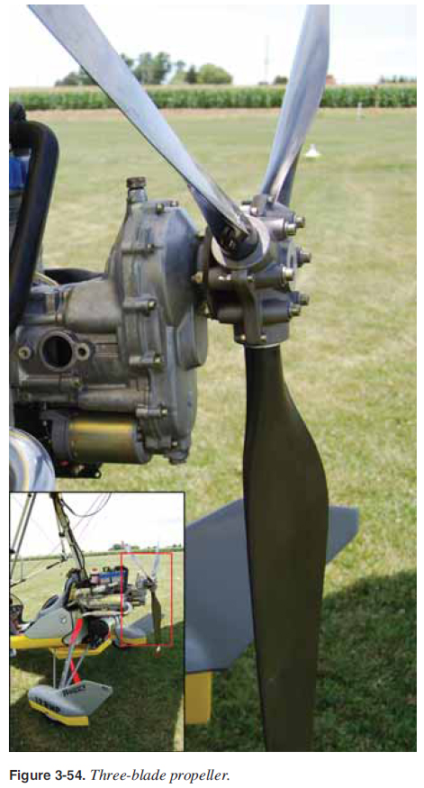 As with an airplane propeller, the WSC aircraft propeller turns at such high speeds that it becomes invisible when in motion. The dangers of a turning propeller require every pilot to maintain the highest level of safety and respect for the consequences of body parts, pets, and debris coming in contact with a rotating propeller. Debris on the takeoff/ landing fi eld is a danger to the propeller, as well as to the people who may be in the prop-wash area behind or on the side of the propeller. Stones, small pieces of metal, and sticks can become dangerous projectiles if kicked into the propeller during start-up, taxi, takeoff, and landing. Just as with any airframe or wing component of a WSC aircraft, if the propeller becomes damaged, nicked, or dinged, the aircraft’s performance can be greatly affected. Some pilots elect to use tape or rock defl ector guards to protect the leading edge from rock/debris damage. Regardless, taking proper care of the propeller is as critical as proper engine and wing care. |
| ©AvStop Online Magazine Contact Us Return To Books |
