ch6
CHAPTER 6 - CONTROL OF LOADING - GENERAL AVIATION
Before any flight, the pilot should determine the weight and balance
condition of the aircraft. In the early days of flying, aircraft were loaded
by guess and intuition. On occasion, the results were grim. Through trial
and error the early pilots learned about weight and balance. Today there
is no excuse for following this method. Simple and orderly procedures based
on sound principles have been devised by aircraft manufacturers for the
determination of loading conditions. The pilot, however, must use these
procedures and exercise good judgment. In many modern aircraft, it is not
possible to fill all seats, baggage compartments, and fuel tanks and still
remain within the approved weight and balance limits. If the maximum passenger
load is carried, the pilot must often reduce the fuel load or reduce the
baggage.
| USEFUL LOAD CHECK
A simple and fundamental weight check should always be made by general
aviation pilots before flight. This check should determine if the useful
load is exceeded. The check may be a mental calculation if the pilot is
familiar with the aircraft's limits and knows that unusually heavy loads
are not aboard. But when all seats are being occupied, fuel tanks are full,
and some baggage is aboard, the pilot should do some careful calculations.
The pilot needs to know the useful load limit of the particular aircraft.
This information may be found in the latest weight and balance report,
in a log book, or on a major repair and alteration form, located in the
aircraft. If useful load is not stated directly, simply subtract empty
weight from maximum takeoff weight. Be especially weight conscious of aircraft
which have a limited useful load because they are the ones which cause
weight and balance troubles. |
|
 |
|
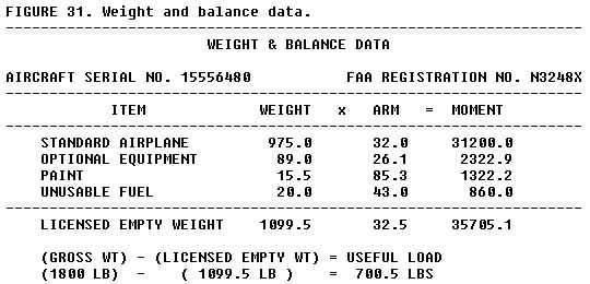
IT IS THE RESPONSIBILITY OF THE OWNER AND PILOT TO ENSURE THAT THE AIRPLANE
IS PROPERLY LOADED. THE DATA ABOVE INDICATES THE EMPTY WEIGHT, C.G., AND
USEFUL LOAD WHEN THE AIRPLANE WAS RELEASED FROM THE FACTORY. REFER TO THE
LATEST WEIGHT AND BALANCE RECORD WHEN ALTERATIONS HAVE BEEN MADE.
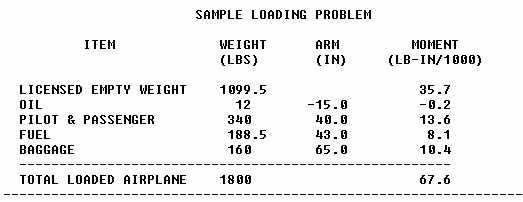
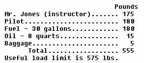
The check is simple enough - just be sure to include all the load items
included in the useful load - then check the total against the limit. The
calculations might look like this:
The calculations indicate that the useful load is not exceeded and the
flight can take place.
Now suppose that Mr. Jones, in the example, is replaced by a new instructor
who weighs 210 lb. A useful load check will show that the aircraft is too
heavy. The pilot in our example must reduce the load to the specified useful
load limit. There is no alternative in this small aircraft but to reduce
the fuel load, even if all the baggage has been removed.
Pilots should be aware of, and on the alert for, unusual loadings. They
should remember that the manufacturer's initial weight and balance calculations
and some examples in the owner's manual make the assumption that the pilot
and passengers weigh a standard 170 lb. each. Heavyweight passengers can
overload a small aircraft seriously. A student and instructor may easily
weigh 220 lb. each in winter clothing; this represents a potential overload
of 100 lb. The baggage compartment is another place where pilot vigilance
should be directed - the maximum compartment load placard must be obeyed.
Frequently, a restriction is placed on rear seat occupancy with the maximum
baggage aboard.
WEIGHT AND BALANCE RESTRICTIONS
Be sure to follow your aircraft's weight and balance restrictions. The
loading conditions and empty weight of your particular aircraft (fig.
31) may differ from those in the owner's manual due to modifications
or equipment changes. Sample loading problems in the owner's manual are
intended for guidance only; each aircraft must be treated separately for
weight and balance. The pilot should understand that although the aircraft
is certified for a specified maximum gross weight, it will not safely take
off with this load under all conditions. Conditions which affect takeoff
and climb performance such as high elevations, high temperatures, and high
humidity (high density altitudes), may require operation at reduced weight.
Other factors to consider are runway length, runway surface, runway slope,
surface wind, and the presence of obstacles. Pilot experience and proficiency
should always be considered - if in doubt, reduce the load.
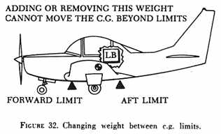
| Some small aircraft are designed so that it is not possible
to load them in a condition which will place the c.g. outside the fore
or aft limits if standard load schedules are observed. These aircraft have
the seats, fuel, and baggage accommodations located very near the c.g.
limits. They also have special empty weight c.g. limits listed in their
specifications. Loads can be added to or removed from any location within
the c.g. range with complete freedom from concern about c.g. movement.
Such action cannot cause the c.g. to move beyond the c.g. limits of these
aircraft (see fig. 32), but maximum weight limits can still be exceeded. |
|
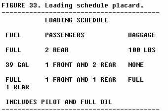
Most aircraft, however, can be loaded in a manner which will place the
c.g. beyond limits. Even though the useful load is not exceeded, an out-of-balance
condition is serious from a stability and control standpoint. The pilot
can quickly determine if the load is within limits, if the aircraft is
simple enough to make use of a loading schedule. This schedule may be found
in the weight and balance report, the aircraft log book, the owner's manual,
or may be posted in the form of a placard. A typical placard may appear
similar to the one shown in figure 33.
The loading schedule should be treated as a suggested loading plan only.
The pilot should make a check by means of weight and balance calculations
to see if limitations are not being exceeded. The assumption in the use
of the loading schedule is that each passenger weighs approximately the
standard weight of 170 lb. It is obvious that passenger weights could vary
widely from the assumed standard.
AIRPLANE FLIGHT MANUAL
Each airplane of over 6,000 lbs. maximum weight is furnished with an
airplane flight manual. An airplane of less than 6,000 lbs. may have information
furnished in the form of placards, markings, or manuals. When an airplane
flight manual is furnished, the following is included:
a. Limitations and data:
(1) The maximum weight.
(2) The empty weight and c.g. location.
(3) The useful load.
(4) The composition of the useful load, including the total weight
of fuel and oil with full tanks.
b. Load distribution:
The established c.g. limits are furnished in the airplane flight manual.
If the available loading space is adequately placarded or arranged so that
no reasonable distribution of the useful load will result in a c.g. outside
of the stated limits, the airplane flight manual may not include any information
other than the statement of c.g. limits. In other cases, the manual includes
enough information to indicate loading combinations that will keep the
c.g. within established limits.
LIGHT SINGLE ENGINE AIRCRAFT LOADING PROBLEMS
| Aircraft manufacturers use one of several available systems
to provide the aircraft loading information. The following weight and balance
problems will show how the pilot can determine if the maximum weight limit
is exceeded or the c.g. is located beyond limits.
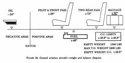
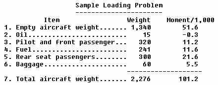
Assume you are a pilot planning a flight in a light single engine, four
place aircraft. Your load consists of yourself, one front seat passenger
and two rear seat passengers, full fuel and oil, and 60 lb. of baggage
(fig. 34). Here is how the critical weight and balance problems are solved
for this case by two different methods (examples 23 and 24). |
|
EXAMPLE 23.
Solution by index table:
1. From the manual or weight and balance report, determine the empty
weight and empty weight c.g. (arm) of the aircraft.
2. Determine the arms for all useful load items.
3. Determine the maximum weight and c.g. range. (For this case - Max.
TOGW = 2,400 lb., c.g. range - Sta. 35.6 to 45.8.)
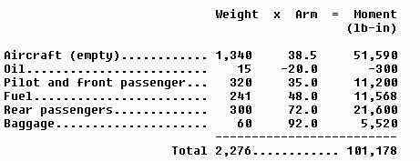
4. Calculate the actual weights for the useful load items.
5. Construct a table as follows, and enter the appropriate values.
Multiply each individual weight and arm to obtain moments.
NOTE - Observe that the oil tank for this aircraft is located forward
of the datum. Care must be taken to subtract the negative oil moment when
totaling the moment column.
6. Adding the weights produces a total of 2,276 lb., and adding the
moments produces a total of 101,178 lb-in. The c.g. is calculated by dividing
the total moment by the total weight:
101,178
------- = 44.5 in aft of datum
2,276
7. The total weight of 2,276 lb. does not exceed the maximum weight
of 2,400 lb., and the computed c.g. of 44.5 falls within the allowable
c.g. range of 35.6 to 45.8 in. aft of datum.
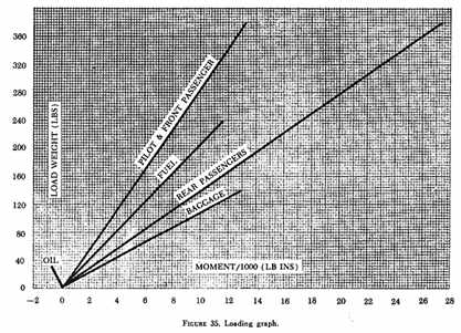
| Weight and balance computations are greatly simplified
by two graphic aids - the loading graph and the center of gravity moment
envelope. The loading graph (fig. 35) is typical of those found in general
aviation aircraft owner's manuals. This graph, in effect, multiplies weight
by arm giving moment, then divides the moment by a reduction factor, giving
an index number. Weight values appear along the left side of the graph.
The moment/1,000 or index numbers are along the bottom. In this example,
each line representing a load item is labeled. To determine the moment
of any load item, find the weight along the left margin, then project a
line right to a point of intersection with the appropriate load item line.
For example, the index number of a pilot weighing 170 lb. is 6.1. |
|
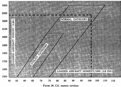
The c.g. moment envelope (fig. 36) allows the pilot to
bypass the computation of a c.g. number. It gives an acceptable range of
index numbers for any aircraft weight from minimum to maximum.
If the lines from total weight and total moment intersect within the
envelope, the aircraft is within weight and balance limits. In solving
the sample problem, follow this procedure:
EXAMPLE 24.
1. Determine the aircraft empty weight and the empty weight index from
the weight and balance report.
2. Construct a table such as the one |
|
that follows. In the left column, enter the actual weights of the
empty aircraft, oil, pilot and front seat passenger, fuel, rear seat passenger,
and baggage. In the right column, enter the aircraft empty weight index
(moment/1,000).
3. From the loading graph, fig. 35, determine the
index number (moment/1,000) of each useful load weight item and enter it
in the table.
4. Add the weight and moment columns and write in the totals.
5. Refer to the c.g. moment envelope, fig. 36, and
find the point of intersection of a line projected right from total weight
(2,276 lbs.) and of a line projected up from total moment/1,000 (101.2).
6. The point of intersection falls within the envelope, therefore, the
weight and c.g. are within limits.
LIGHT TWIN ENGINE AIRCRAFT
Modern light twin engine aircraft are larger than most single engine
aircraft; accordingly, their useful load is almost always greater than
that found in the smaller aircraft. In these aircraft, it is possible to
have many different loading combinations. Their large baggage compartments
may be full or empty, and there may be wide variations in the number of
seats being occupied. These variations are to be expected and are normal
for the types of operations for which the aircraft are used. However, the
c.g. is bound to range backward and forward as the loads are varied; therefore,
weight and balance control is essential.
If a variety of loads can be placed aboard an aircraft in a number of
locations, the pilot must be especially aware of duties regarding weight
and balance control. Pilots should use a reliable weight and balance system,
preferably the type recommended by the manufacturer, to assure that the
weight and balance is within limits for each flight. They should insist
that passengers are assigned to the correct seat from a weight distribution
standpoint. They should also be sure that passenger baggage or miscellaneous
cargo is properly loaded.
The weight and balance systems used on light twin engine aircraft are
essentially the same as those used for single engine aircraft. Weights,
arms, and moments are the basic factors, and the final c.g. computation
must fall within the allowable c.g. limits. Many twin engine aircraft make
use of the loading graph and moment envelope system (figs. 35
and 36). Other models make use of index tables similar
to those explained earlier for single engine aircraft (fig.
24).
Some light twin engine aircraft have weight and balance control systems
which make use of a special weight and balance plotter. The typical plotter
is made of plastic material similar to an aeronautical computer. It consists
of several movable parts which can be adjusted over a plotting board on
which is printed a c.g. envelope. The reverse side of the typical plotter
contains general loading recommendations for the particular aircraft. The
recommendations may suggest that occupants be loaded progressively from
front to rear. In other words, the forward and center seats should be occupied
before passengers are assigned to the rear seats. A pencil line plot can
be made directly on the envelope imprinted on the working side of the plotting
board. This plot can be erased and recalculated anew for each flight. The
plotter is to be used only for the aircraft for which it was designed.
This weight and balance control system is very similar to one used on air
carrier aircraft as illustrated by figure 57.
A typical weight and balance plotter should contain this reminder: "It
is the responsibility of the owner and pilot to ascertain that the aircraft
always remains within the allowable weight versus c.g. envelope while in
flight." This note should serve as a precaution to the pilot to be sure
to check the weight and balance condition before takeoff and to be sure
that any shift in passenger seating locations does not adversely affect
the location of the aircraft center of gravity.
HIGH DENSITY SEATING AIRCRAFT
Many light twin engine aircraft are being used for transportation of
passengers, cargo, or mail in the form of commuter or air taxi service
to supplement the scheduled and unscheduled air carriers. An increasing
number of twin engine aircraft are being used to carry mail on a scheduled
basis. Many commuter and air taxi operators carry passengers to and from
small cities to make connections with trunk carriers at airports in large
cities. The aircraft used for this purpose are in some cases fitted with
a large number of seats in relation to fuselage size and are called high
density seating aircraft. The aircraft may contain seats for eight to 15
passengers and some of the larger types may seat over 25 passengers. The
loading problems are relatively more complex than for aircraft which carry
only six passengers. The complexity of the loading situation approaches
that encountered in air carrier operations. Weight and balance limits for
high density seating aircraft must be respected. The passenger, cargo,
or mail load on high density seating aircraft may vary considerably from
flight to flight. Some trips may be made with a full load and others with
a minimum load. Some of the high density seating aircraft have special
weight and balance problems because they have been modified and modernized
from older aircraft which originally did not have a great number of seats.
Some of these modified aircraft are very sensitive as far as loading toward
the rear limit is concerned. The recommended weight and balance checking
procedures for modified aircraft must be carefully followed and operators
should be sure to make a thorough analysis of weight and balance records
to assure currency.
An operator's manual, when required for high density seating aircraft,
should contain procedures for assuring compliance with weight and balance
limits, including periodic reweighing of the aircraft. The weight and balance
procedures contained in the manual should:
1. Be based on sound principles, using standardized terminology, and
be compatible with the type(s) of aircraft operated.
2. When followed, assure that the aircraft is properly loaded and will
not exceed authorized weight and balance limitations during operation.
3. Provide for blocking off seats or compartments when necessary to
remain within c.g. limits. Effective means should be provided to assure
that those seats and compartments are not occupied during operations specified.
4. Provide crewmembers, cargo handlers, and other personnel concerned
complete information regarding distribution of passengers, fuel, and other
items, and should give complete information regarding the distribution
and security of cargo to prevent the shifting of weight in flight.
5. Provide other information relative to maximum weights, capacities,
and other pertinent limitations affecting the weight and balance of the
aircraft.
Pilots of these high density seating aircraft must be aware of the effect
of passenger and cargo location on c.g., and they must have a personal
knowledge of the means of correcting an out-of-limits condition. They often
have no one to assist them with loading problems; they act as pilot, dispatcher,
and loading agent in many cases.
In commuter or air taxi operations, pilots are confronted with the problem
of frequent trips with varying loads. They need to have a positive, accurate,
and fast way to compute the weight and balance. They must have reliable
empty weight and c.g. information readily available for use. This information
must be updated to account for all the modifications performed on the aircraft.
A load manifest, when required for air taxi or commercial operations,
should contain the following information concerning the aircraft loading
at takeoff time:
1. The weight of the aircraft, fuel and oil, cargo (including mail and
baggage), and passengers;
2. The maximum allowable weight for that flight;
3. The total weight computed under approved procedures;
4. Evidence that the aircraft is loaded according to an approved schedule
that insures that the c.g. is within approved limits.
 |
|
The execution of a load manifest is always a highly recommended procedure
from the standpoint of making a uniform preflight check of the weight and
balance condition. A typical load manifest may be a simple form similar
to that illustrated in figure 37. This form provides
a record of passengers and of all useful loads for the particular flight.
The major advantage of such a form is that the pilot has a standardized
means of calculating and recording the weight and balance condition of
the aircraft for each flight. If care is taken to carry forward or make
proper record of the empty weight and c.g., the pilot can be spared the
task of a search through aircraft records for this vital information. The
form may also be used as a record of passenger identification as may be
needed for administrative purposes.
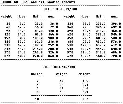
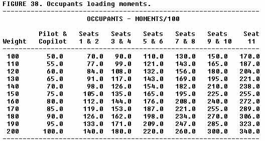
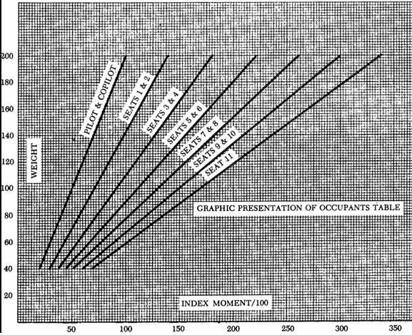
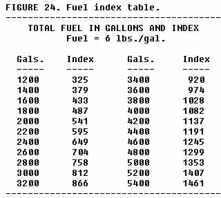
One typical weight and balance control system for high density seating
aircraft is based upon the utilization of useful load index tables and
a total weight index limit envelope or table. With these tables (figs.
38, 39, 40, 41),
it is possible to determine if weight and balance is within limits even
in a situation where the passenger, cargo, or fuel loads change fairly
rapidly. The tables can be read for intermediate weights by interpolation
of values. To simplify and speed up calculations, use the nearest listed
weight, but be conservative when checking against particular limits. The
system is generally similar to those discussed on smaller aircraft. The
pilot adds the weight and moments (index) of the empty aircraft and the
useful load items. Then, checks are made against the published limits in
this case the index limit envelope or table. Care must be taken to use
the empty weight and moments or index from the latest weight and balance
report. The pilot must be sure to use the same reduction factor for all
moments in the calculations. Sufficient accuracy is obtained by rounding
off index numbers to the nearest tenth.
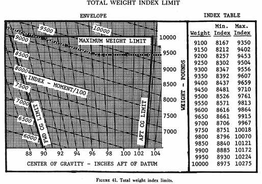
EXAMPLE 25.
Assume you are a pilot planning a flight in an air taxi aircraft. Your
load consists of yourself, your copilot, 11 passengers, 300 pounds of fuel
in each of the main tanks, 120 pounds of fuel in each of the auxiliary
tanks, 75 pounds of oil, 100 pounds of baggage in the nose compartment,
and 200 pounds of baggage in the rear compartment. The sample manifest
form in figure 37 has been completed to show the
useful load and empty weight items. Use the loading tables and total weight
index limit table shown in figures 38, 39,
40, 41 to determine if the aircraft
is properly loaded for takeoff. The intersection of the dotted weight and
moment/100 lines in figure 41 shows that limits are
not being exceeded.
TWIN ENGINE CARGO AIRCRAFT
Small twin engine aircraft can be used effectively for carrying cargo
into airports where operations would not be practical with transport aircraft.
Cargo which is particularly suitable for twin engine aircraft are high
value items or items which must reach local destinations quickly. The scheduled
transportation of mail to small cities and towns is an example of the type
service these aircraft provide.
Light twin engine aircraft can be designed for more effective cargo
operations if some special loading and handling features are employed.
Large size cargo doors are a great help when bulky packages are to be loaded.
Without the use of large doors, the cargo space may be restricted because
big packages cannot be maneuvered through the passenger type doors. Provisions
for securing the cargo to the aircraft structure are also needed. Normally,
tiedown rings are attached to the floor and to structural members of the
side walls for this purpose.
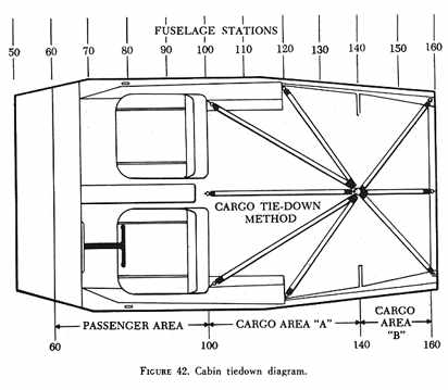
Many of the high density twin engine aircraft can be quickly converted
from passenger to cargo use by removing the seats from the main cabin area
(fig. 42). In some cases, cargo is carried in the
passenger seats and secured by the regular seat belt. It is also possible
that only one or two passenger seats will be removed, resulting in a mixture
of cargo and passengers in the main cabin. Measures must be taken in this
case to protect the passengers from possible cargo movement.
The following are recommended for the loading of cargo in other than
approved cargo compartments or bins:
a. If passengers are carried, the cargo must be carried forward of the
foremost passenger.
b. The cargo should be properly secured by a safety belt or other tiedown
device to prevent it from becoming a hazard by shifting.
c. The cargo must not impose any load on seats or the floor structure
that exceeds the load limitations for these components.
d. The location of the cargo must not restrict access to or use of any
required emergency or regular exit by any passenger, or access to an emergency
exit by a pilot if a regular exit is not accessible to the pilot.
e. The location of the cargo must not obscure any passenger's view of
any required sign, unless an auxiliary sign or other approved means for
proper instruction or notification is provided.
Cabin cargo is in danger of shifting if the deck angle (floor attitude)
is not level as during the rotation and initial climb at takeoff. Unrestrained
cargo will shift rearward in this event and cause a tail-heavy condition
which may lead to a dangerous takeoff stall. Cabin cargo is also subjected
to inertia forces resulting from turbulence, acceleration, deceleration,
vibration, and hard landings. These inertia forces act more strongly in
some directions than in others and tend to shift the cargo unless it is
properly restrained. A forward force is the one most likely to act on cargo.
This force may result from a sudden application of brakes, landing on a
soft sod runway, or a crash landing. That is why cargo should be located
forward of all passengers in a mixed-load configuration. Cargo must also
be secured from moving aft, from side to side (laterally), or up and down
(vertically).
Cargo may be secured by means of tiedown devices such as straps, ropes,
or nets. These devices, when properly used, will restrain the cargo from
moving in any direction. Tiedown fittings should be adequate in number
and strength to restrain a cargo of any allowable weight and size. Floor
structure, particularly where the tiedown fittings are anchored, must be
strong enough to resist any anticipated load without distortion. Cargo
floor loading limits are usually expressed as maximum weight in pounds
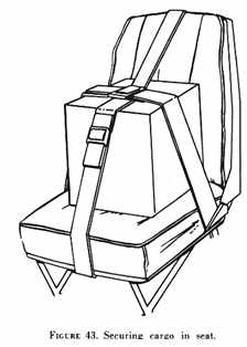
per square foot. If a cargo item is loaded in a seat, the pilot would be
wise to limit its weight to that of an average passenger. A tiedown or
safety belt should restrain its movement in the seat (fig.
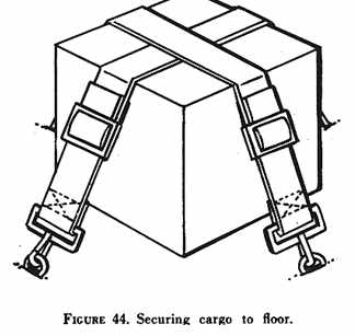
43). A single cargo item on the cabin floor should be secured in a
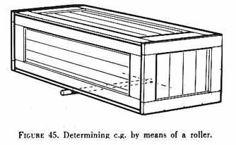
manner similar to that shown in figure 44. Its center
of gravity may be determined by the method shown in figure 45.
The following general precautions should be observed when actually loading
the cargo:
1. In a tailwheel aircraft, cylindrical items on their sides should
be chocked until lashed down.
2. Liquid containers should be placed with their outlets at the top.
3. Lightweight items should be stacked on heavier items, or stacked
separately.
4. Shoring or planking must be used when the contact area is likely
to exceed the floor strength limitations.
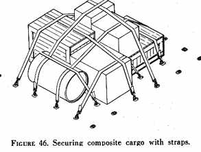
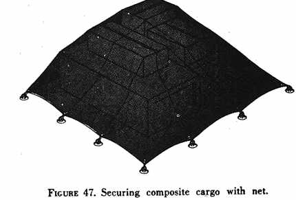
Many cargo loads carried in air taxi aircraft will consist of a variety
of boxes, crates, sacks, drums, etc. This type of composite cargo may be
secured with the type devices shown in figures 46
and 47. Sufficient restraint should be used to prevent
shifting because of high deck angle or inertia forces. In arranging composite
loads, cargo items should not be arranged so the load is top-heavy. If
possible, the height of the load should not exceed its length. Particular
care should be taken to secure this type load against slipping out from
under the tiedown device. If the individual items of this type cargo are
comparatively light, a net type tiedown device is adequate. Heavy items
will require ropes or straps.
Cargo should be placed as near to the c.g. of the airplane as possible,
roughly at the 30% chord point; but limitations of particular areas should
be observed to prevent overloading the structure. Care must also be taken
not to block access to an exit in the rear of the cabin or to cut off an
aisle needed for inflight inspection of the main cabin cargo.
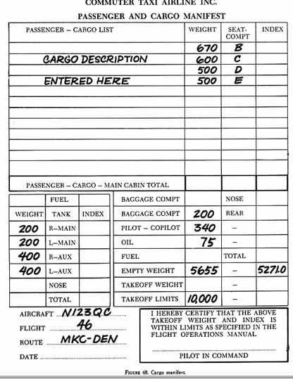
EXAMPLE 26.
This problem is an example of the use of a manifest form to determine
the weight and balance condition of a cargo flight. The airplane is the
same one used in example 25 with the seats removed from the main cabin.
Notice that the empty weight and moments have been changed due to the removal
of the seats. This change must be carefully noted according to the manufacturer's
recommendations. The sample manifest form in figure 48
has been completed to show the useful load and empty weight items.
Using the loading tables and total weight index table shown in figures
38, 39, 40, 41
to determine the loading condition of the aircraft, you should obtain a
moment of 10038.7 index units. It is apparent when the index limit table
is checked that the cargo is loaded too far to the rear. The aircraft is
not safe or legal to fly in this loaded condition. The maximum index limit
(rear c.g. limit) has been exceeded by 20.7 index units (2070.0 lb-in).
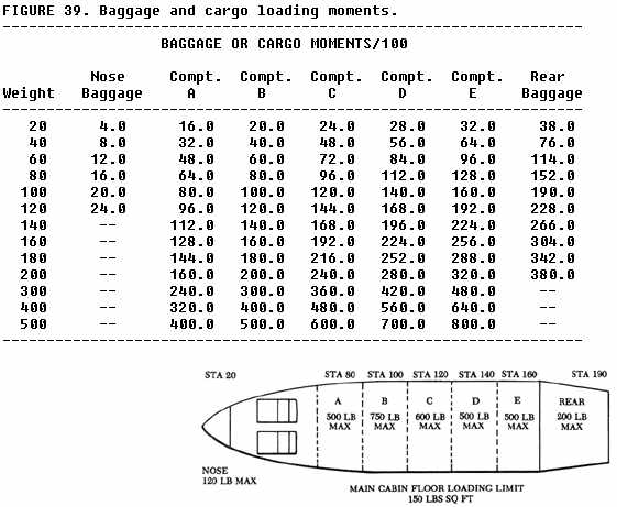
If the cargo in compartment E consists of cartons, each weighing 20 pounds,
how many cartons must be moved to compartment A to bring the index within
the maximum limit?
The baggage or cargo table can be used to help determine how much cargo
must be shifted. At least two methods are available:
1. Select the cargo weight which would make a difference of at least
20.7 index units when compartments A and E are compared. (40 lb. = 64.0
- 32.0 = 32.0 index units)
2. Determine the difference in arms between compartments A and E (Sta.
160 - Sta. 80 = 80 inch). Divide the excessive moments by this arm (2070.0
/ 80 = 25.9 lb.).
By use of either method we can see that the movement of 40 lb. (two
each 20 lb cartons) would be required to reduce the index by at least 20.7.
A new passenger and cargo manifest should now be executed to prove that
the c.g. is within limits with the proposed new load distribution. Of course,
it would be possible to shift a greater number of cartons than the minimum
to be on the safe side. In any case, care must be taken to remain within
the compartment maximum weight limit, the floor loading limit, and the
minimum and maximum index limits.
HELICOPTER WEIGHT AND BALANCE
The weight and balance principles and procedures which have been described
in connection with airplanes apply generally to helicopters. Each model
helicopter is certificated for a specific maximum gross weight. However,
it is not safe to operate at this maximum weight under all conditions.
Combinations of high altitude, high temperature, and high humidity determine
the density altitude at a particular location. This, in turn, critically
affects the hovering, takeoff, climb, autorotation, and landing performance
of a helicopter. Additional factors to be considered are wind, obstacles,
type of surface, and space available for takeoff and landing. Just because
a helicopter can take off with a heavy load does not mean that flight with
that load will be safe. A heavily loaded helicopter has less ability to
withstand shocks and additional airloads caused by turbulence. The greater
the weight, the less the margin of safety for the supporting structures
such as the main rotor, fuselage, and landing gear.
Most helicopters have a much more restricted c.g. range than do airplanes.
In some cases this range is less than 3 inches. The exact location and
length of the c.g. range is specified for each helicopter and usually extends
a short distance fore and aft of the main rotor mast or the centroid of
a dual rotor system. Ideally, the helicopter should have such perfect balance
that the fuselage remains horizontal while in a hover and the only cyclic
adjustment required should be that made necessary by the wind. The fuselage
acts as a pendulum suspended from the rotor. Any change in the c.g. changes
the angle at which it hangs from this point of support. Many recently designed
helicopters have loading compartments and fuel tanks located at or near
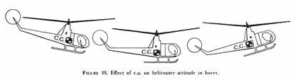
the balance point. If the helicopter is not loaded properly and the c.g.
is not very near the balance point, the fuselage does not hang horizontal
in a hover. If the c.g. is too far aft, the nose tilts up and excessive
forward cyclic is required to maintain a stationary hover. Conversely,
if the c.g. is too far forward, the nose tilts down and excessive aft cyclic
is required (fig. 49). In extreme out-of-balance conditions,
full fore or aft cyclic may be insufficient to maintain control. Similar
lateral balance problems may be encountered if external loads are carried.
Upon delivery by the manufacturer, the empty weight, empty weight c.g.,
and the useful load are noted on the weight and balance data sheet in the
helicopter flight manual. If, after delivery additional fixed equipment
is added or removed, or if a major repair or alteration is made which may
affect the empty weight, empty weight c.g., or useful load, the weight
and balance data must be revised. All weight and balance changes should
be entered in the appropriate aircraft record. The helicopter flight manual
includes directions for solving loading problems. The procedures are similar
to those already described for airplanes. For further information, read
the FAA Basic Helicopter Handbook, AC
61-13A.
