Load factor is the ratio of the total load supported by the airplane’s wing to the actual weight of the airplane and its contents; i.e., the actual load supported by the wings divided by the total weight of the airplane. For example, if an airplane has a gross weight of 2,000 pounds and during flight is subjected to aerodynamic forces which increase the total load the wing must support to 4,000 pounds, the load factor would be 2.0 (4,000/2,000 = 2). In this example, the airplane wing is producing “lift” that is equal to twice the gross weight of the airplane.
Another way of expressing load factor is the ratio of a given load to the pull of gravity; i.e., to refer to a load factor of three, as “3 G’s,” where “G” refers to the pull of gravity. In this case the weight of the airplane is equal to “1 G,” and if a load of three times the actual weight of the airplane were imposed upon the wing due to curved flight, the load factor would be equal to “3 G’s.”
To be certificated by the Federal Aviation Administration (FAA), the structural strength (load factor) of airplanes must conform with prescribed standards set forth by Title 14 of the Code of Federal Regulations (14 CFR).
All airplanes are designed to meet certain strength requirements depending upon the intended use of the airplanes. Classification of airplanes as to strength and operational use is known as the category system.
The category of each airplane can be readily identified by a placard or document (Airworthiness Certificate) in the cockpit which states the operational category or categories in which that airplane is certificated.
The category, maneuvers that are permitted, and the maximum safe load
factors (limit load factors) specified for these airplanes are listed in
figure 1-32.
| Category Permissible Maneuvers Limit load Factor*
Normal
Utility
Acrobatic No restrictions except those shown to be necessary as a 6.0
result of required flight tests.
|
It should be noted that there is an increase in limit load factor
with an increasing severity of maneuvers permitted. Small airplanes may
be certificated in more than one category if the requirements for each
category are met.
This system provides a means for the pilot to determine what
operations can be performed in a given airplane without exceeding the load
limit. Pilots are cautioned to operate the airplane within the load limit
for which the airplane is designed so as to enhance safety and still benefit
from the intended utilization of the airplane.
Effect of Turns on Load Factor
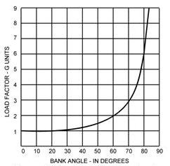
A turn is made by banking the airplane so that lift from the wings pulls the airplane from its straight flightpath. It is not within the scope of this handbook to discuss the mathematics of the turn. However, in any airplane at any airspeed, if a constant altitude is maintained during the turn, the load factor for a given degree of bank is the same. For any given angle of bank, the rate of turn varies with the airspeed. In other words, if the angle of bank is held constant and the airspeed is increased, the rate of turn will decrease; or if the airspeed is decreased, the rate of turn will increase. Because of this, there is no change in centrifugal force for any given bank. Therefore, the load factor remains the same.
It should also be noted how rapidly load factor increases as the angle of bank approaches 90°. The 90° banked, constant altitude turn is not mathematically possible. An airplane can be banked to 90°, but a continued coordinated turn is impossible at this bank angle without losing altitude.
|
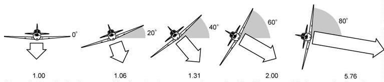
| The load supported by the wings increases as the angle
of bank increases. The increase is shown by the relative lengths of the
white arrows. Figures below the arrows indicate the increase in load factor.
For example, the load factor during a 60° bank is 2.00, and the load
supported by the wings is twice the weight of the airplane in level flight.
Figures 1-33 and 1-34 reveal an important fact about load factor in turns. The load factor increases at a rapid rate after the angle of bank reaches 50°. The wing must produce lift equal to this load factor if altitude is to be maintained. At an angle of bank of slightly more than 80°, the load factor exceeds
6, which is the limit load factor of an acrobatic airplane.
|
 |
|
|