A detailed discussion of the propeller is quite complex and beyond the intended scope of this handbook. However, the following material is offered as an introduction to the function of the propeller.
A propeller is a rotating airfoil, and is subject to induced drag, stalls, and other aerodynamic principles that apply to any airfoil. It provides the necessary thrust to pull, or in some cases push, the airplane through the air. This is accomplished by using engine power to rotate the propeller which in turn generates thrust in much the same way as a wing produces lift. The propeller has an angle of attack which is the angle between the chord line of the propeller’s airfoil and its relative wind (airflow opposite to the motion of the blade).
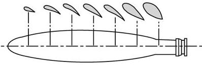
| A propeller blade is twisted. The blade angle changes from the hub to the tip with the greatest angle of incidence, or highest pitch, at the hub and the smallest at the tip. [Figure 2-10] The reason for the twist is to produce uniform lift from the hub to the tip. As the blade rotates, there is a difference in the actual speed of the various portions of the blade. |
|
| Figure 2-10.—Changes in propeller blade angle from hub to tip. |
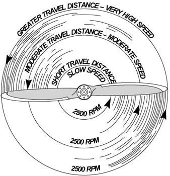 |
The tip of the blade travels faster than that part near the hub because
the tip travels a greater distance than the hub in the same length of time.
Changing the angle of incidence (pitch) from the hub to the tip to correspond
with the speed produces uniform lift throughout the length of the blade.
If the propeller blade was designed with the same angle of incidence throughout
its entire length, it would be extremely inefficient because as airspeed
increases in flight, the portion near the hub would have a negative angle
of attack while the blade tip would be stalled. [Figure 2-11]
|
| Figure 2-11.—Relationship of travel distance and speed of various portions of propeller blade. |
| Geometric pitch is the distance in inches that the propeller would move forward in one revolution if it were rotated in a solid medium so as not to be affected by slippage as it is in the air. Effective pitch is the actual distance it moves forward through the air in one revolution. Propeller slip is the difference between the geometric pitch and effective pitch. Pitch is proportional to the blade angle which is the angle between the chord line of the blade and the propeller’s plane of rotation. [Figure 2-12] |
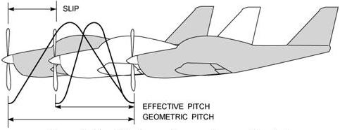 |
| Figure 2-12.—Effective and geometric propeller pitch. |
Fixed-Pitch Propeller
The pitch of this propeller is fixed by the manufacturer and cannot be changed by the pilot. There are two types of fixed-pitch propellers; the climb propeller and the cruise propeller. Whether the airplane has a climb or cruise propeller installed depends upon its intended use. The climb propeller has a lower pitch, therefore less drag. This results in the capability of higher RPM and more horsepower being developed by the engine. This increases performance during takeoffs and climbs, but decreases performance during cruising flight.
The cruise propeller has a higher pitch, therefore more drag. This results in lower RPM and less horsepower capability. This decreases performance during takeoffs and climbs, but increases efficiency during cruising flight.
The propeller on a low-horsepower engine is usually mounted on a shaft which may be an extension of the engine crankshaft. In this case, the RPM of the propeller would be the same as the engine RPM.
On higher horsepower engines, the propeller is mounted on a shaft geared to the engine crankshaft. In this type, the RPM of the propeller is different than that of the engine.
If the propeller is a fixed-pitch and the speed of the engine
and propeller is the same, a tachometer is the only indicator of engine
power.
A tachometer is calibrated in hundreds of RPM, and gives a direct
indication of the engine and propeller RPM. The instrument is color coded
with a green arc denoting the normal operating range and a red line denoting
the maximum continuous operating RPM. Some tachometers have additional
marking or interrupted arcs. Therefore, the manufacturer’s recommendations
should be used as a reference to clarify any misunderstanding of tachometer
markings.
The revolutions per minute are regulated by the throttle which controls the fuel/air flow to the engine. At a given altitude, the higher the tachometer reading the higher the power output of the engine.
There is a condition under which the tachometer does not show correct power output of the engine. This occurs when operating altitude increases. For example, 2,300 RPM at 5,000 feet produce less horsepower than 2,300 RPM at sea level. The reason for this is that air density decreases as altitude increases. Power output depends on air density, therefore decreasing the density decreases the power output of the engine. As altitude changes, the position of the throttle must be changed to maintain the same RPM. As altitude is increased, the throttle must be opened further to indicate the same RPM as at a lower altitude.
Controllable-Pitch Propellers
The pitch on these propellers can be changed in flight; therefore,
they are referred to as controllable-pitch propellers. These propeller
systems vary from a simple two-position propeller to more complex automatic
constant-speed propellers.
The number of pitch positions at which the propeller can be set
may be limited, such as a two-position propeller with only high or low
pitch available. Many other propellers, however, are variable pitch, and
can be adjusted to any pitch angle between a minimum and maximum pitch
setting.
An airplane equipped with a controllable-pitch propeller has two
controls: (1) a throttle control and (2) a propeller control.
The throttle controls the power output of the engine which is
registered on the manifold pressure gauge. The manifold pressure gauge
is a simple barometer that measures the air pressure in the engine intake
manifold in inches of mercury. It is color coded with a green arc indicating
the normal operating range.
The propeller control regulates the engine RPM and in turn the propeller RPM. The RPM is registered on the tachometer. The pilot can set the throttle control and propeller control at any desired manifold pressure and RPM setting within the engine operating limitation.
Within a given power setting, when using a constant-speed propeller, the pilot can set the propeller control to a given RPM and the propeller governor will automatically change the pitch (blade angle) to counteract any tendency for the engine to vary from this RPM. For example, if manifold pressure or engine power is increased, the propeller governor automatically increases the pitch of the blade (more propeller drag) to maintain the same RPM.
A controllable-pitch propeller permits the pilot to select the
blade angle that will result in the most efficient performance for a particular
flight condition. A low blade angle or decreased pitch, reduces the propeller
drag and allows more engine power for takeoffs. After airspeed is attained
during cruising flight, the propeller blade is changed to a higher angle
or increased pitch.
Consequently, the blade takes a larger bite of air at a lower
power setting, and therefore increases the efficiency of the flight. This
process is similar to shifting gears in an automobile from low gear to
high gear.
For any given RPM there is a manifold pressure that should not be exceeded. If manifold pressure is excessive for a given RPM, the pressure within the cylinders could be exceeded, thus placing undue stress on them. If repeated too frequently, this stress could weaken the cylinder components and eventually cause engine failure.
The pilot can avoid conditions that would possibly overstress the cylinders by being constantly aware of the RPM, especially when increasing the manifold pressure. Pilots should conform to the manufacturer’s recommendations for power settings of a particular engine so as to maintain the proper relationship between manifold pressure and RPM. Remember, the combination to avoid is a high throttle setting (manifold pressure indication) and a low RPM (tachometer indication).
When both manifold pressure and RPM need to be changed, the pilot can further help avoid engine overstress by making power adjustments in the proper order. When power settings are being decreased, reduce manifold pressure before RPM. When power settings are being increased, reverse the order—increase RPM first, then manifold pressure. If RPM is reduced before manifold pressure, manifold pressure will automatically increase and possibly exceed the manufacturer’s tolerances.
Summarizing:
In an airplane equipped with a controllable-pitch propeller, the throttle controls the manifold pressure and the propeller control is used to regulate the RPM. Avoid high manifold pressure settings with low RPM. The preceding is a standard procedure for most situations, but with unsupercharged engines it is sometimes modified to take advantage of auxiliary fuel metering devices in the carburetor. These devices function at full throttle settings, providing additional fuel flow. This additional fuel helps cool the engine during takeoffs and full power climbs where engine overheating may be a problem. In such instances, a small reduction in RPM is possible without overstressing the engine, even though the throttle is in the full-power position. If in doubt, the manufacturer’s recommendations should be followed.