Electrical energy is required to operate navigation and communication
radios, lights, and other airplane equipment.
Many airplanes in the past were not equipped with an electrical
system. They were equipped with a magneto system which supplied electrical
energy to the engine ignition system only. Modern airplanes still use an
independent magneto system, but in addition are equipped with an electrical
system. The magneto system does not depend upon the airplane electrical
system for operation. In other words, the airplane electrical system can
be turned off in flight and the engine will continue to operate efficiently,
utilizing the electrical energy provided by the magnetos.
Most airplanes are equipped with a 14- or 28-volt direct-current
electrical system. The 28-volt system provides an electrical reserve capacity
for more complex systems, including additional electrical energy for starting.
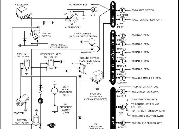
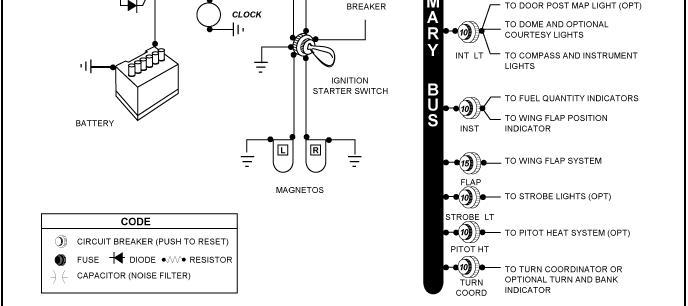
A basic airplane electrical system consists of the following
components:
• Alternator or generator
• Battery
• Master or battery switch
• Alternator or generator switch
• Bus bar, fuses, and circuit breakers
• Voltage regulator
• Ammeter
• Starting motor
• Associated electrical wiring
• Accessories
Engine-driven alternators or generators supply electric current to
the electrical system and also maintain a sufficient electrical charge
in the battery which is used primarily for starting.
There are several basic differences between alternators and generators.
Most generators will not produce a sufficient amount of electrical current
at low engine revolutions per minute (RPM) to operate the entire electrical
system. Therefore, during operations at low engine RPM’s, the electrical
needs must be drawn from the battery, which in a short time may be depleted.
An alternator, however, produces a sufficient amount of electrical
current at slower engine speeds by first producing alternating current
which is converted to direct current. Another advantage is that the electrical
output of an alternator is more constant throughout the ranges of engine
speeds. Alternators are also lighter in weight, less expensive to maintain,
and less prone to become overloaded during conditions of heavy electrical
loads.
Electrical energy stored in a battery provides a source of electricity for starting the engine and a limited supply of electricity for use in the event the alternator or generator fails.
Some airplanes are equipped with receptacles to which external auxiliary power units (APU) can be connected to provide electrical energy for starting. These are very useful, especially during cold weather starting. Care must be exercised in starting engines using an APU.
A master switch is installed on airplanes to provide a means for the pilot to turn the electrical system “on” and “off.” Turning the master switch “on” provides electrical energy to all the electrical equipment circuits with the exception of the ignition system. Although additional electrical equipment may be found in some airplanes, the following lists the equipment most commonly found which uses the electrical system for its source of energy:
• Position lights
• Landing lights
• Interior cabin lights
• Radio equipment
• Fuel gauges
• Stall warning system
• Anticollision lights
• Taxi lights
• Instrument lights
• Turn indicator
• Electric fuel pump
• Pitot heat
Some airplanes are equipped with a battery switch which controls
the electrical power to the airplane in a manner similar to the master
switch. In addition, an alternator switch is installed which permits the
pilot to exclude the alternator from the electrical system in the event
of alternator failure. With the alternator switch “off,” the entire electrical
load is placed on the battery. Therefore, all nonessential electrical equipment
should be turned off to conserve the energy stored in the battery.
|
|
|
|
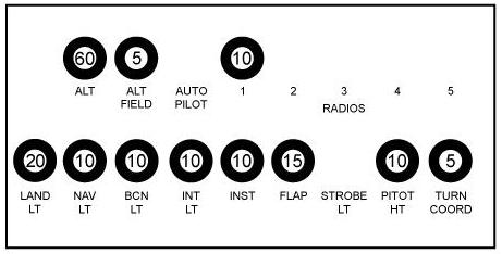
| Fuses or circuit breakers are used in the electrical system
to protect the circuits and equipment from electrical overload. Spare fuses
of the proper amperage limit should be carried in the airplane to replace
defective or blown fuses. Circuit breakers have the same function as a
fuse but can be manually reset, rather than replaced, if an overload condition
occurs in the electrical system. Placards at the fuse or circuit breaker
location identify the circuit by name and show the amperage limit. [Figure
2-3]
An ammeter is an instrument used to monitor the performance of the airplane electrical system. Not all airplanes are equipped with an ammeter. Some are equipped with a light which, when lighted, indicates a discharge in the system as a generator/alternator malfunction. |
 |
|
|
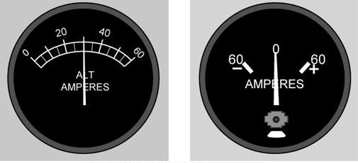 |
An ammeter shows if the alternator/generator is producing an adequate supply of electrical power to the system by measuring the amperes of electricity. This instrument also indicates whether the battery is receiving an electrical charge. The face of some ammeters is designed with a zero point in the upper center of the dial and a plus value to the right of center; a negative value is to the left. A vertical needle swings to the right or left, depending upon the performance of the electrical system. If the needle indicates a plus value, it means that the battery is being charged. After power is drawn from the battery for starting, the needle will indicate a noticeable plus charge value for a short period of time, and then stabilize to a lower plus charge value. [Figure 2-4] |
|
|
The loadmeter type of ammeter shows the load being placed on the alternator. [Figure 2-4]
A voltage regulator controls the rate of charge to the battery by stabilizing the generator or alternator electrical output. The generator/alternator voltage output is usually slightly higher than the battery voltage. For example, a 12-volt battery would be fed by a generator/alternator system of approximately 14 volts. The difference in voltage keeps the battery charged.