 |
Knowledge of a few general principles of engine operation will help the pilot obtain increased dependability and efficiency from the engine and, in many instances, this knowledge will help in avoiding engine failure.
In this short chapter, it is impractical to discuss in detail the various types of engines and the finer points of operation which can be learned only through experience. Information from the manufacturer’s instruction manual; familiarity with the operating limitations for the airplane engine; and specific advice from a flight instructor, combined with the information contained within this section, should provide adequate information to operate an airplane engine satisfactorily.
|
How an Engine Operates
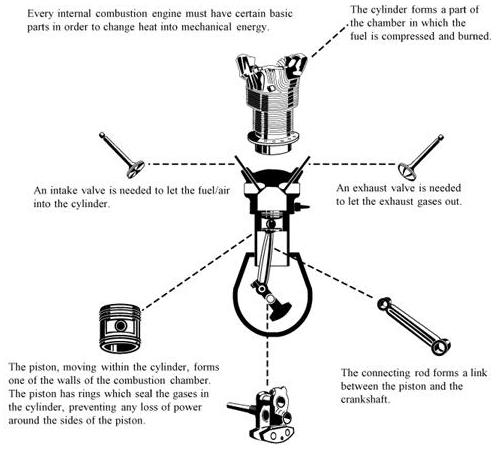
Most light airplane engines are internal combustion of the reciprocating type which operate on the same principle as automobile engines. They are called reciprocating engines because certain parts move back and forth in contrast to a circular motion such as a turbine. Some smaller airplanes are equipped with turbine engines, but this type will not be discussed in this handbook. As shown in figure 2-5, the reciprocating engine consists of cylinders, pistons, connecting rods, and a crankshaft. One end of a connecting rod is attached to a piston and the other end to the crankshaft.
This connecting rod converts the straight-line motion of the piston to the rotary motion of the crankshaft, which turns the propeller. At the closed end of the cylinder, there are normally two spark plugs which ignite the fuel, and two openings over which valves open and close. One valve (the intake valve) when open admits the mixture of fuel and air, and the other (the exhaust valve) when open permits the burned gases to escape. For the engine to complete one cycle, the piston must complete four strokes. This requires two revolutions of the crankshaft. The four strokes are the intake, compression, power, and exhaust.
The following describes one cycle of engine operation.
 |
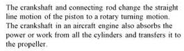
| Figure 2-6.—Four strokes of the piston produce: (A) fuel mixture (light blue) is drawn into cylinder by downward stroke, (B) mixture (darker blue) is compressed by upward stroke, (C) spark ignites mixture (red) forcing piston downward and producing power that turns propeller, (D) burned gases (light red) pushed out of cylinder by upward stroke. |
Diagram A of figure 2-6 shows the piston moving away from the cylinder head. The intake valve is opened and the fuel/air mixture is drawn into the cylinder. This is the intake stroke.
Diagram B shows the piston returning to the top of the cylinder. Both valves are closed, and the fuel/air mixture is compressed. This is the compression stroke.
Diagram C shows that when the piston is approximately at the top of the cylinder head, a spark from the plugs ignites the mixture, which burns at a controlled rate. Expansion of the burning gas exerts pressure on the piston, forcing it downward. This is the power stroke.
Diagram D shows that just before the piston completes the power stroke the exhaust valve starts to open, and the burned gases are forced out as the piston returns to the top of the cylinder. This is the exhaust stroke. The cycle is then ready to begin again as shown in Diagram A.
From this description, notice that each cylinder of the engine
delivers power only once in every four strokes of the piston or every two
revolutions of the crankshaft. The momentum of the crankshaft carries the
piston through the other three strokes although the diagram shows the action
of only one cylinder. To increase power and gain smoothness of operation,
other cylinders are added and the power strokes are timed to occur at successive
intervals during the revolution of the crankshaft.
Aircraft engines are classified by the various ways the cylinders
are arranged around the central crankcase. Most general aviation airplane
engines are classed as the horizontally opposed, which have the cylinder
banks arranged in two rows, directly opposite to each other and using the
same crankshaft.
Larger and more powerful reciprocating engines are classed as radial engines. In these engines, the cylinders are placed in a circular pattern around the crankcase, which is placed in the center of the circle.
Other engine classifications are the in-line engine with the cylinders placed in one straight row, and the “vee” type with the cylinders placed in two rows forming a “V” similar to the V-8 engine used in automobiles.
Cooling System
The burning fuel within the cylinders produces intense heat, most of which is expelled through the exhaust. Much of the remaining heat, however, must be removed to prevent the engine from overheating. In practically all automobile engines, excess heat is carried away by a coolant circulating around the cylinder walls.
Most light airplane engines are air cooled. The cooling process is accomplished by cool air being forced into the engine compartment through openings in front of the engine cowl. This ram air is routed by baffles over fins attached to the engine cylinders, and other parts of the engine, where the air absorbs the engine heat. Expulsion of the hot air takes place through one or two openings at the rear bottom of the engine cowling.
Some airplanes are equipped with a device known as cowl flaps which are used to control engine temperatures during various flight operations. Cowl flaps are hinged covers which fit over the opening through which the hot air is expelled. By adjusting the cowl flap opening, the pilot can regulate the engine temperature during flight. If the engine temperature is low, the cowl flaps can be closed, thereby restricting the flow of expelled hot air and increasing engine temperature. If the engine temperature is high, the cowl flaps can be opened to permit a greater flow of air through the system, thereby decreasing the engine temperature. Usually during low airspeed and high power operations such as takeoffs and climbs, the cowl flaps are opened. During higher speed and lower power operations such as cruising flight and descents, the cowl flaps are closed.
Under normal operating conditions in airplanes not equipped with cowl flaps, the engine temperature can be controlled by changing the airspeed or the power output of the engine. High engine temperatures can be decreased by increasing the airspeed and/or reducing the power.
The oil temperature gauge indicates the temperature of the oil which is heated by the engine; therefore, this gauge gives an indirect and delayed indication of rising engine temperature. However, the oil temperature gauge should be used for determining engine temperature if this is the only means available.
Many airplanes are equipped with a cylinder-head temperature gauge. This is an additional instrument which will indicate a direct and immediate cylinder temperature change. This instrument is calibrated in degrees Celsius or Fahrenheit, and is usually color coded with a green arc to indicate the normal operating range. A red line on the instrument indicates maximum allowable cylinder head temperature.
To avoid excessive cylinder head temperatures, a pilot can open the cowl flaps, increase airspeed, enrich the mixture, or reduce power. Any of these procedures will aid in reducing the engine temperature.
When an airplane engine is operated on the ground, very little air flows past the cylinders (particularly if the engine is closely cowled) and overheating is likely to occur. Overheating may also occur during a prolonged climb, because the engine at this time is usually developing high power at relatively slow airspeed.
Operating the engine at higher than its designed temperature can cause loss of power, excessive oil consumption, and detonation. It will also lead to serious permanent damage, such as, scoring the cylinder walls, damaging the pistons and rings, and burning and warping the valves. To aid the pilot in avoiding excessive temperatures, engine temperature instruments in the cockpit should be monitored in flight.