2-9
Fuel System
The function of the fuel system is to provide a means of storing fuel
in the airplane and transferring this fuel to the airplane engine. Fuel
systems are classified according to the method used to furnish fuel to
the engine from the fuel tanks. The two classifications are the “gravity
feed” and the “fuel pump system.”
The gravity feed system utilizes the force of gravity to transfer the
fuel from the tanks to the engine. This system can be used on high-wing
airplanes if the fuel tanks are installed in the wings. This places the
fuel tanks above the carburetor and the fuel is gravity fed through the
system and into the carburetor.
If the design of the airplane is such that gravity cannot be used to
transfer fuel, fuel pumps are installed. This is true on low-wing airplanes
where the fuel tanks in the wings are located below the carburetor.
Two fuel pump systems are used on most airplanes. The main pump system
is engine driven and an auxiliary electric driven pump is provided for
use in the event the engine pump fails. The auxiliary pump, commonly know
as the “boost pump,” provides added reliability to the fuel system, and
is also used as an aid in engine starting. The electric auxiliary pump
is controlled by a switch in the cockpit.
Because of variation in fuel system operating procedures, the pilot
should consult the Aircraft Flight Manual or Pilot’s Operating Handbook
for specific operating procedures.
Fuel Tanks, Selectors, Strainers, and Drains
Most airplanes are designed to use space in the wings to mount fuel
tanks. All tanks have filler openings which are covered by a cap. This
system also includes lines connecting to the engine, a fuel gauge, strainers,
and vents which permit air to replace the fuel consumed during flight.
Fuel overflow vents are provided to discharge fuel in the event the fuel
expands because of high temperatures. Fuel tank sump drains are located
at the bottom of the tanks from which water and other sediment can be drained
from the tanks.
Fuel lines pass through a selector assembly located in the cockpit which
provides a means for the pilot to turn the fuel “off,” “on,” or to select
a particular tank from which to draw fuel. The fuel selector assembly may
be a simple “on/off” valve, or a more complex arrangement which permits
the pilot to select individual tanks or use all tanks at the same time.
Airplanes are equipped with fuel strainers, called sumps, located at
the low point in the fuel lines between the fuel selector and the carburetor.
The strainer filters the fuel and traps water and sediment in a container
which can be drained to remove foreign matter from the fuel.
Fuel Primer
A manual fuel primer is installed in some airplanes to aid in starting
the engine, particularly when the weather is cold. Activating the primer
draws fuel from the tanks and vaporizes the fuel directly into the cylinders
through small fuel lines. When engines are cold and do not generate sufficient
heat to vaporize the fuel, the primer is used not only to start the engine,
but to keep the engine running until sufficient engine heat is generated.
Fuel Pressure Gauge
If a fuel pump is installed in the fuel system, a fuel pressure gauge
is also included. This gauge indicates the pressure in the fuel lines.
The normal operating pressure can be found in the Airplane Flight Manual
or on the gauge by color coding.
Induction, Carburetion, and Injection Systems
In reciprocating aircraft engines, the function of the induction system
is to complete the process of taking in outside air, mixing it with fuel,
and delivering this mixture to the cylinders. The system includes the air
scoops and ducts, the carburetor or fuel injection system, the intake manifold,
and (if installed) the turbo or superchargers.
Two types of induction systems are commonly used in light airplane engines:
(1) carburetor system, which mixes the fuel and air in the carburetor before
this mixture enters the intake manifold, and (2) fuel injection system
in which the fuel and air are mixed just prior to entering each cylinder.
The fuel injection system does not utilize a carburetor.
Carburetor System
| The carburetor system uses one of two types of carburetor:
(1) the float-type carburetor, which is generally installed in airplanes
equipped with small horsepower engines, and (2) the pressure type, used
in higher horsepower engines. The pressure type will not be discussed in
this handbook, but many aspects of each are similar.
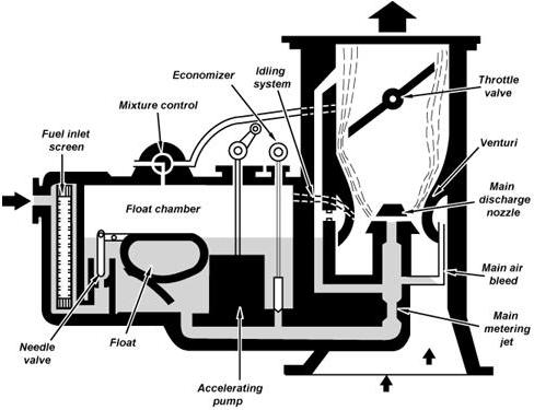
In the operation of the carburetor system, the outside air first flows
through an air filter, usually located at an air intake in the front part
of the engine cowling. This filtered air flows into the carburetor and
through a venturi, a narrow throat in the carburetor. When the air flows
through the venturi, a low pressure area is created, which forces the fuel
to flow through a main fuel jet located at the throat and into the airstream
where it is mixed with the flowing air. [Figure 2-7] |
 |
|
Figure 2-7.—A float-type carburetor.
|
The fuel/air mixture is then drawn through the intake manifold and into
the combustion chambers where it is ignited. The “float-type carburetor”
acquires its name from a float which rests on fuel within the float chamber.
A needle attached to the float opens and closes an opening in the fuel
line. This meters the correct amount of fuel into the carburetor, depending
upon the position of the float, which is controlled by the level of fuel
in the float chamber. When the level of the fuel forces the float to rise,
the needle closes the fuel opening and shuts off the fuel flow to the carburetor.
It opens when the engine requires additional fuel.