8-6
FLIGHT PLANNING
Title 14 of the Code of Federal Regulations (14 CFR) part 91 states,
in part, that before beginning a flight, the pilot in command of an aircraft
shall become familiar with all available information concerning that flight.
For flights not in the vicinity of an airport, this must include information
on available current weather reports and forecasts, fuel requirements,
alternatives available if the planned flight cannot be completed, and any
known traffic delays reported by air traffic control (ATC).
Careful preflight planning is extremely important. With adequate
planning, the pilot can complete the flight with greater confidence, ease,
and safety. Statistics show inadequate preflight planning is a significant
cause of fatal accidents.
Assembling Necessary Material
The pilot should collect the necessary material well before the
flight to be sure nothing is missing. An appropriate current sectional
chart and charts for areas adjoining the flight route should be among this
material if the route of flight is near the border of a chart.
Additional equipment should include a flight computer or electronic
calculator, plotter, and any other item appropriate to the particular flight—for
example, if a night flight is to be undertaken, carry a flashlight; if
a flight is over desert country, carry a supply of water and other necessities.
Weather Check
It may be wise to check the weather before continuing with other
aspects of flight planning to see, first of all, if the flight is feasible
and, if it is, which route is best. Chapter 5 on weather discusses obtaining
a weather briefing.
Use of the Airport/Facility Directory
Study available information about each airport at which a landing
is intended. This should include a study of the Notices to Airmen (NOTAMs)
and the Airport/Facility Directory. This includes location, elevation,
runway and lighting facilities, available services, availability of aeronautical
advisory station frequency (UNICOM), types of fuel available (use to decide
on refueling stops), AFSS/FSS located on the airport, control tower and
ground control frequencies, traffic information, remarks, and other pertinent
information. The NOTAMs, issued every 14 days, should be checked for additional
information on hazardous conditions or changes that have been made since
issuance of the Airport/Facility Directory.
The sectional chart bulletin subsection should be checked for
major changes that have occurred since the last publication date of each
sectional chart being used. Remember, the chart may be up to 6 months old.
The effective date of the chart appears at the top of the front of the
chart.
The Airport/Facility Directory will generally have the latest
information pertaining to such matters and should be used in preference
to the information on the back of the chart, if there are differences.
Airplane Flight Manual or Pilot’s Operating Handbook
The Airplane Flight Manual or Pilot’s Operating Handbook should
be checked to determine the proper loading of the airplane (weight and
balance data). The weight of the usable fuel and drainable oil aboard must
be known. Also, check the weight of the passengers, the weight of all baggage
to be carried, and the empty weight of the airplane to be sure that the
total weight does not exceed the maximum allowable. The distribution of
the load must be known to tell if the resulting center of gravity is within
limits. Be sure to use the latest weight and balance information in the
FAA-approved Airplane Flight Manual or other permanent aircraft records,
as appropriate, to obtain empty weight and empty weight center-of-gravity
information.
Determine the takeoff and landing distances from the appropriate
charts, based on the calculated load, elevation of the airport, and temperature;
then compare these distances with the amount of runway available. Remember,
the heavier the load and the higher the elevation, temperature, or humidity,
the longer the takeoff roll and landing roll and the lower the rate of
climb.
Check the fuel consumption charts to determine the rate of fuel
consumption at the estimated flight altitude and power settings. Calculate
the rate of fuel consumption, then compare it with the estimated time for
the flight so that refueling points along the route can be included in
the plan.
 |
CHARTING THE COURSE
Once the weather has been checked and some preliminary planning
done, it is time to chart the course and determine the data needed to accomplish
the flight. The following sections will provide a logical sequence to follow
in charting the course, filling out a flight log, and filing a flight plan.
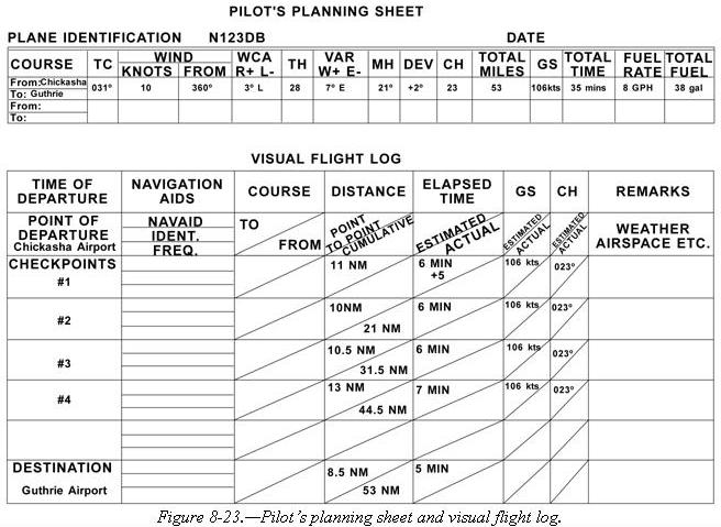
In the following example, a trip is planned based on the following data
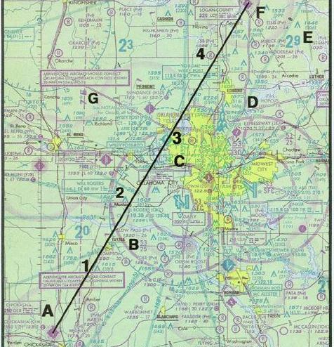
and the sectional chart excerpt in figure 8-22.
Route of flight: Chickasha Airport direct to Guthrie Airport
-
True Airspeed (TAS) 115 knots
-
Winds Aloft 360° at 10 knots
-
Usable fuel 38 gallons
-
Fuel Rate 8 GPH
-
Deviation +2°
Steps in Charting the Course
The following is a suggested sequence for arriving at the pertinent
information for the trip. As information is |
| Figure 8-22.—Sectional chart excerpt. |
|
determined, it may be noted as illustrated in the example of a flight log
in figure 8-23. Where calculations are required, the pilot may use a mathematical
formula or a manual or electronic flight computer. If unfamiliar with how
to use a manual or electronic computer competently, it would be advantageous
to read the operation manual and work several practice problems at this
point.
First draw a line from Chickasha Airport (point A) directly to
Guthrie Airport (point F). The course line should begin at the center of
the airport of departure and end at the center of the destination airport.
If the route is direct, the course line will consist of a single straight
line. If the route is not direct, it will consist of two or more straight
line segments—for example, a VOR station which is off the direct route,
but which will make navigating easier, may be chosen (radio navigation
is discussed later in this chapter).
Appropriate checkpoints should be selected along the route and
noted in some way. These should be easy-to-locate points such as large
towns, large lakes and rivers, or combinations of recognizable points such
as towns with an airport, towns with a network of highways and railroads
entering and departing, etc. Normally, choose only towns indicated by splashes
of yellow on the chart. Do not choose towns represented by a small circle—these
may turn out to be only a half-dozen houses. (In isolated areas, however,
towns represented by a small circle can be prominent checkpoints.) For
this trip, four checkpoints have been selected. Checkpoint 1 consists of
a tower located east of the course and can be further identified by the
highway and railroad track which almost parallels the course at this point.
Checkpoint 2 is the obstruction just to the west of the course and can
be further identified by Will Rogers Airport which is directly to the east.
Checkpoint 3 is Wiley Post Airport which the aircraft should fly directly
over. Checkpoint 4 is a private non-surfaced airport to the west of the
course and can be further identified by the railroad track and highway
to the east of the course.
The course and areas on either side of the planned route should
be checked to determine if there is any type of airspace with which the
pilot should be concerned or which has special operational requirements.
For this trip, it should be noted that the course will pass through a segment
of the Class C airspace surrounding Will Rogers Airport where the floor
of the airspace is 2,500 feet mean sea level (MSL) and the ceiling is 5,300
feet MSL (point B). Also, there is Class D airspace from the surface to
3,800 feet MSL surrounding Wiley Post Airport (point C) during the time
the control tower is in operation.
Study the terrain and obstructions along the route. This is necessary
to determine the highest and lowest elevations as well as the highest obstruction
to be encountered so that an appropriate altitude which will conform to
part 91 regulations can be selected. If the flight is to be flown at an
altitude more than 3,000 feet above the terrain, conformance to the cruising
altitude appropriate to the direction of flight is required. Check the
route for particularly rugged terrain so it can be avoided. Areas where
a takeoff or landing will be made should be carefully checked for tall
obstructions. TV transmitting towers may extend to altitudes over 1,500
feet above the surrounding terrain. It is essential that pilots be aware
of their presence and location. For this trip, it should be noted that
the tallest obstruction is part of a series of antennas with a height of
2,749 feet MSL (point D). The highest elevation should be located in the
northeast quadrant and is 2,900 feet MSL (point E).
Since the wind is no factor and it is desirable and within the
airplane’s capability to fly above the Class C and D airspace to be encountered,
an altitude of 5,500 feet MSL will be chosen. This altitude also gives
adequate clearance of all obstructions as well as conforms to the part
91 requirement to fly at an altitude of odd thousand plus 500 feet when
on a magnetic course between 0 and 179°.
Next, the pilot may want to measure the total distance of the
course as well as the distance between checkpoints. The total distance
is 53 NM and the distance between checkpoints is as noted on the flight
log in figure 8-23.
After determining the distance, the true course should be measured.
If using a plotter, follow the directions on the plotter. The true course
is 031°. Once the true heading is established, the pilot can determine
the compass heading. This is done by following the formula given earlier
in this chapter. The formula is:
TC ± WCA = TH ± VAR = MH ± DEV = CH
The wind correction angle can be determined by using a manual
or electronic flight computer. Using a wind of 360° at 10 knots, it
is determined the WCA is 3° left. This is subtracted from the TC making
the TH 28°. Next, the pilot should locate the isogonic line closest
to the route of the flight to determine variation. Point G in figure 8-22
shows the variation to be 7° E which means it should be subtracted
from the TH giving an MH of 21°. Next, add 2° to the MH for the
deviation correction. This gives the pilot the compass heading which is
23°.
Next, the groundspeed should be determined. This can be done using
a manual or electronic calculator. It is determined the GS is 106 knots.
Based on this information, the total trip time, as well as time between
checkpoints, and the fuel burned can be determined. These calculations
can be done mathematically or by using a manual or electronic calculator.
For this trip, the GS is 106 knots and the total time is 35 minutes
(30 minutes plus 5 minutes for climb) with a fuel burn of 4.7 gallons.
Refer to the flight log in figure 8-23 for the time between checkpoints.
As the trip progresses, the pilot can note headings and time and
make adjustments in heading, groundspeed, and time.