8-8
RADIO NAVIGATION
Most airplanes flown in today’s environment are equipped with
radios that provide a means of navigation and communication with ground
stations.
Advances in navigational radio receivers installed in airplanes,
the development of aeronautical charts which show the exact location of
ground transmitting stations and their frequencies, along with refined
cockpit instrumentation make it possible for pilots to navigate with precision
to almost any point desired. Although precision in navigation is obtainable
through the proper use of this equipment, beginning pilots should use this
equipment to supplement navigation by visual reference to the ground (pilotage).
If this is done, it provides the pilot with an effective safeguard against
disorientation in the event of radio malfunction.
There are four radio navigation systems available for use for
VFR navigation. These are:
• VHF Omnidirectional Range (VOR)
• Nondirectional Radiobeacon (NDB)
• Long Range Navigation (LORAN-C)
• Global Positioning System (GPS)
Very High Frequency (VHF) Omnidirectional Range (VOR)
The word “omni” means all, and an omnidirectional range is a VHF
radio transmitting ground station that projects straight line courses (radials)
from the station in all directions. From a top view, it can be visualized
as being similar to the spokes from the hub of a wheel. The distance VOR
radials are projected depends upon the power output of the transmitter.
The course or radials projected from the station are referenced
to magnetic north. Therefore, a radial is defined as a line of magnetic
bearing extending outward from the VOR station. Radials are identified
by numbers beginning with 001, which is 1° east of magnetic north,
and progress in sequence through all the degrees of a circle until reaching
360. To aid in orientation, a compass rose reference to magnetic north
is superimposed on aeronautical charts at the station location.
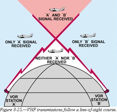
| VOR ground stations transmit within a VHF frequency band
of 108.0 - 117.95 MHz. Because the equipment is VHF, the signals transmitted
are subjected to line-of-sight restrictions. Therefore, its range varies
in direct proportion to the altitude of receiving equipment. Generally,
the reception range of the signals at an altitude of 1,000 feet above ground
level is about 40 to 45 miles. This distance increases with altitude. [Figure
8-25]
For the purpose of this discussion, the term “VOR” will be used to include
both VOR and VORTAC. Briefly, a VORTAC station provides, in addition to
azimuth information, range information. If the airplane is equipped with
distance measuring equipment (DME), the distance from the station in nautical
miles is displayed on the instrument.
VORs and VORTACs are classed according to operational use. There
are three classes:
• T (Terminal)
• L (Low altitude)
• H (High altitude) |
|
The useful range of certain facilities may be less than 50 miles. For
further information concerning these restrictions, refer to the Comm/NAVAID
Remarks in the Airport/Facility Directory.
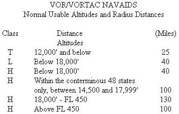
| The normal useful range for the various classes is shown
in the following table: |
|
 |
The accuracy of course alignment of VOR radials is considered to be
excellent. It is generally within plus or minus 1°. However, certain
parts of the VOR receiver equipment deteriorate, and this affects its accuracy.
This is particularly true at great distances from the VOR station. The
best assurance of maintaining an accurate VOR receiver is periodic checks
and calibrations. VOR accuracy checks are not a regulatory requirement
for VFR flight. However, to assure accuracy of the equipment, these checks
should be accomplished quite frequently along with a complete calibration
each year. The following means are provided for pilots to check VOR accuracy:
• FAA VOR test facility (VOT);
• certified airborne checkpoints; and
• certified ground checkpoints located on airport surfaces. |
A list of these checkpoints is published in the Airport/Facility
Directory. Basically, these checks consist of verifying that the VOR radials
the airplane equipment receives are aligned with the radials the station
transmits. There are not specific tolerances in VOR checks required for
VFR flight. But as a guide to assure acceptable accuracy, the required
IFR tolerances can be used which are ±4° for ground checks and
±6° for airborne checks. These checks can be performed by the
pilot.
The VOR transmitting station can be positively identified by its
Morse code identification or by a recorded voice identification which states
the name of the station followed by the word “VOR.” Many Flight Service
Stations transmit voice messages on the same frequency that the VOR operates.
Voice transmissions should not be relied upon to identify stations, because
many FSS’s remotely transmit over several omniranges which have different
names than the transmitting FSS. If the VOR is out of service for maintenance,
the coded identification is removed and not transmitted. This serves to
alert pilots that this station should not be used for navigation. VOR receivers
are designed with an alarm flag to indicate when signal strength is inadequate
to operate the navigational equipment. This happens if the airplane is
too far from the VOR or the airplane is too low and therefore, is out of
the line-of-sight of the transmitting signals.
Using the VOR
Using the VOR is quite simple once the basic concept is understood.
The following information, coupled with practice in actually using this
equipment, should erase all the mysteries and also provide a real sense
of security in navigating with the VOR.
In review, for VOR radio navigation, there are two components
required: the ground transmitter and the aircraft receiving equipment.
The ground transmitter is located at specific positions on the ground and
transmits on an assigned frequency. The aircraft equipment includes a receiver
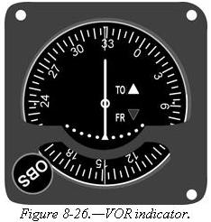
with a tuning device and a VOR or omninavigation instrument. The navigation
instrument consists of (1) an omnibearing selector (OBS) sometimes referred
to as the course selector, (2) a course deviation indicator needle (Left-Right
Needle), and (3) a TO-FROM indicator.
| The course selector is an azimuth dial that can be rotated
to select a desired radial or to determine the radial over which the aircraft
is flying. In addition, the magnetic course “TO” or “FROM” the station
can be determined.
When the course selector is rotated, it moves the course deviation indicator
or needle to indicate the position of the radial relative to the aircraft.
If the course selector is rotated until the deviation needle is centered,
the radial (magnetic course “FROM” the station) or its reciprocal (magnetic
course “TO” the station) can be determined. The course deviation needle
will also move to the right or left if the aircraft is flown or drifting
away from the radial which is set in the course selector.
By centering the needle, the course selector will indicate either the
course “FROM” the station or the course “TO” the station. If the flag displays
a “TO,” the course shown on the course selector must be flown to the station.
If “FROM” is displayed and the course shown if followed, the aircraft will
be flown away from the station. [Figure 8-26] |
|
Tracking with Omni
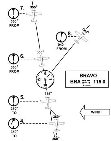
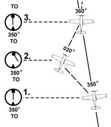
The following describes a step-by-step procedure to use when tracking
to and from a VOR station. Figure 8-27 illustrates the discussion:
• First, tune the VOR receiver to the frequency of the selected VOR
station. For example: 115.0 to receive Bravo VOR. Next, check the identifiers
to verify that the desired VOR is being received. As soon as the VOR is
properly tuned, the course deviation needle will deflect either left or
right; then rotate the azimuth dial to the course selector until the course
deviation needle centers and the TO-FROM indicates “TO.” If the needle
centers with a “FROM” indication, the azimuth should be rotated 180°
because, in this case, it is desired to fly “TO” the station. Now, turn
the aircraft to the heading indicated on the omni azimuth dial or course
selector. In this example 350°.
• If a heading of 350° is maintained with a wind from the right
as shown, the airplane will drift to the left of the intended track. As
the airplane drifts off course, the VOR course deviation needle will gradually
move to the right of center or indicate the direction of the desired radial
or track.
• To return to the desired radial, the aircraft heading must be altered
approximately 30° to the right. As the aircraft returns to the desired
track, the deviation needle will slowly return to center. When centered,
the aircraft will be on the desired radial and a left turn must be made
toward, but not to the original heading of 350° because a wind drift
correction must be established. The amount of correction depends upon the
strength of the wind. If the wind velocity is unknown, a trial and error
method can be used to find the correct heading. Assume, for this example
a 10° correction or a heading of 360° is maintained.
• While maintaining a heading of 360°, assume that the course deviation
begins to move to the left. This means that the wind correction of 10°
is too great and the airplane is flying to the right of course. A slight
turn to the left should be made to permit the airplane to return to the
desired radial.
• When the deviation needle centers, a small wind drift correction of
5° or a heading correction of 355° should be flown. If this correction
is adequate, the airplane will remain on the radial. If not, small variation
in heading should be made to keep the needle centered, and consequently
keep the airplane on the radial.
• As the VOR station is passed, the course deviation needle will fluctuate
then settle down, and the “TO” indication will change to “FROM.” If the
aircraft passes to one side of the station, the needle will deflect in
the direction of the station as the indicator changes to “FROM.”
• Generally, the same techniques apply when tracking outbound as those
used for tracking inbound. If the intent is to fly over the station and
track outbound on the reciprocal of the inbound radial, the course selector
should not be changed. Corrections are made in the same manner to keep
the needle centered. The only difference is that the omni will indicate
“FROM.”
• If tracking outbound on a course other than the reciprocal of the
inbound radial, this new course or radial must be set in the course selector
and a turn made to intercept this course. After this course is reached,
tracking procedures are the same as previously discussed.
Tips on Using the VOR
• Positively identify the station by its code or voice identification.
• Keep in mind that VOR signals are “line-of-sight.” A weak signal
or no signal at all will be received if the aircraft is too low or too
far from the station.
Figure 8-27.—Tracking a radial in a crosswind.
• When navigating to a station, determine the inbound radial and use
this radial. If the aircraft drifts, do not reset the course selector,
but correct for drift and fly a heading that will compensate for wind drift.
• If minor needle fluctuations occur, avoid changing headings immediately.
Wait momentarily to see if the needle recenters; if it doesn’t, then correct.
• When flying “TO” a station, always fly the selected course with a
“TO” indication. When flying “FROM” a station, always fly the selected
course with a “FROM” indication. If this is not done, the action of the
course deviation needle will be reversed. To further explain this reverse
action, if the aircraft is flown toward a station with a “FROM” indication
or away from a station with a “TO” indication, the course deviation needle
will indicate in an opposite direction to that which it should. For example,
if the aircraft drifts to the right of a radial being flown, the needle
will move to the right or point away from the radial. If the aircraft drifts
to the left of the radial being flown, the needle will move left or in
the opposite direction of the radial.
Automatic Direction Finder
Many general aviation-type airplanes are equipped with automatic
direction finder (ADF) radio receiving equipment. To navigate using the
ADF, the pilot tunes the receiving equipment to a ground station known
as a NONDIRECTIONAL RADIOBEACON (NDB). The NDB stations normally operate
in a low or medium frequency band of 200 to 415 kHz. The frequencies are
readily available on aeronautical charts or in the Airport/Facility Directory.
All radiobeacons except compass locators transmit a continuous
three-letter identification in code except during voice transmissions.
A compass locator, which is associated with an Instrument Landing System,
transmits a two-letter identification.
Standard broadcast stations can also be used in conjunction with
ADF. Positive identification of all radio stations is extremely important
and this is particularly true when using standard broadcast stations for
navigation.
Nondirectional radiobeacons have one advantage over the VOR. This
advantage is that low or medium frequencies are not affected by line-of-sight.
The signals follow the curvature of the Earth; therefore, if the aircraft
is within the range of the station, the signals can be received regardless
of altitude.
The following table gives the class of NDB stations, their power,
and usable range:
NONDIRECTIONAL RADIOBEACON (NDB)
(Usable Radius Distances for All Altitudes)
Class Power (Watts) Distance (Miles)
Compass Locator Under 25 15
MH Under 50 25
H 50 - 1999 *50
HH 2000 or more 75
* Service range of individual facilities may be less than 50 miles.
| One of the disadvantages that should be considered when
using low frequency for navigation is that low-frequency signals are very
susceptible to electrical disturbances, such as lighting. These disturbances
create excessive static, needle deviations, and signal fades. There may
be interference from distant stations. Pilots should know the conditions
under which these disturbances can occur so they can be more alert to possible
interference when using the ADF.
Basically, the ADF aircraft equipment consists of a tuner, which is
used to set the desired station frequency, and the navigational display.
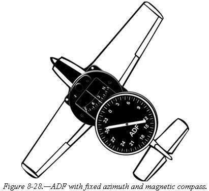
The navigational display consists of a dial upon which the azimuth
is printed, and a needle which rotates around the dial and points to the
station to which the receiver is tuned.
Some of the ADF dials can be rotated so as to align the azimuth
with the aircraft heading, others are fixed with 0° representing the
nose of the aircraft, and 180° representing the tail. Only the fixed
azimuth dial will be discussed in this handbook. [Figure 8-28] |
|
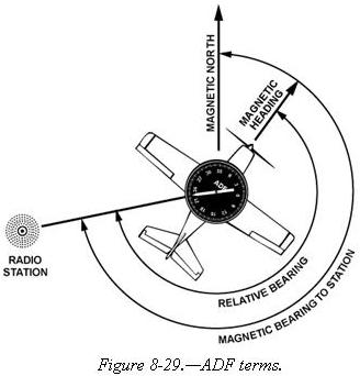 |
Figure 8-29 illustrates the following terms that are used with the
ADF and should be understood by the pilot.
• Relative Bearing—is the value to which the indicator (needle)
points on the azimuth dial. When using a fixed dial, this number is relative
to the nose of the aircraft and is the angle measured clockwise from the
nose of the aircraft to a line drawn from the aircraft to the station.
• Magnetic Bearing —“TO” the station is the angle formed by a
line drawn from the aircraft to the station and a line drawn from the aircraft
to magnetic north. The magnetic bearing to the station can be determined
by adding the relative bearing to the magnetic heading of the aircraft.
For example, if the relative bearing is 060° and the magnetic heading
is 130°, the magnetic bearing to the station is 060° plus 130°
or 190°. This means that in still air a magnetic heading of approximately
190° would be flown to the station. If the total is greater than 360°,
subtract 360° from the total to obtain the magnetic bearing to the
station. For example, if the relative bearing is 270° and magnetic
heading is 300°, 360° is subtracted from the total, or 570°
– 360° = 210°, which is the magnetic bearing to the station. |
To determine the magnetic bearing “FROM” the station, 180° is added
to or subtracted from the magnetic bearing to the station. This is the
reciprocal bearing and is used when plotting position fixes.
Keep in mind that the needle of fixed azimuth points to the station
in relation to the nose of the aircraft. If the needle is deflected 30°
to the left or a relative bearing of 330°, this means that the station
is located 30° left. If the aircraft is turned left 30°, the needle
will move to the right 30° and indicate a relative bearing of 0°
or the aircraft will be pointing toward the station. If the pilot continues
flight toward the station keeping the needle on 0°, the procedure is
called homing to the station. If a crosswind exists, the ADF needle will
continue to drift away from zero. To keep the needle on zero, the aircraft
must be turned slightly resulting in a curved flightpath to the station.
Homing to the station is a common procedure, but results in drifting downwind,
thus lengthening the distance to the station.
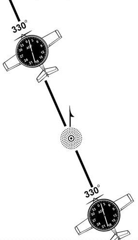
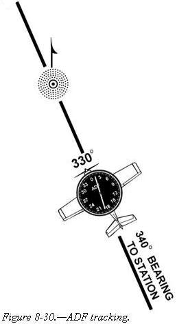
Tracking to the station requires correcting for wind drift and results
in maintaining flight along a straight track or bearing to the station.
When the wind drift correction is established, the ADF needle will indicate
the amount of correction to the right or left. For instance, if the magnetic
bearing to the station is 340°, a correction for a left crosswind would
result in a magnetic heading of 330°, and the ADF needle would indicate
10° to the right or a relative bearing of 010°. [Figure 8-30]
 |
 |
When tracking away from the station, wind corrections are made similar
to tracking to the station but the ADF needle points toward the tail of
the aircraft or the 180° position on the azimuth dial. Attempting to
keep the ADF needle on the 180° position during winds results in the
aircraft flying a curved flight leading further and further from the desired
track. To correct for wind when tracking outbound, correction should be
made in the direction opposite of that in which the needle is pointing.
Although the ADF is not as popular as the VOR for radio navigation,
with proper precautions and intelligent use, the ADF can be a valuable
aid to navigation.
Other Navigational Systems
There are other navigational systems which are more advanced such
as long range navigation (LORAN-C) and global positioning system (GPS).
The long range navigation uses a network of land-based radio transmitters
developed to provide an accurate system for long range navigation. The
system is based upon the measurement of the difference in time of arrival
of pulses of radio-frequency energy radiated by a group or chain of transmitters
which are separated by hundreds of miles.
The global positioning system is a satellite-based radio positioning,
navigation, and time-transfer system developed by the U.S. Department of
Defense. The concept of GPS is based on accurate and continuous knowledge
of the spatial position of each satellite in the system. GPS provides accurate
information 24 hours a day and is unaffected by the weather.
If more detailed information on these systems is desired, the
pilot may reference the Aeronautical Information Manual. Since both LORAN
and GPS have various presentations, a pilot should refer to the Aircraft
Flight Manual for the individual make and model for proper usage.