![]()
|
|
||
| CHAPTER 2. Electronic Flight Instruments
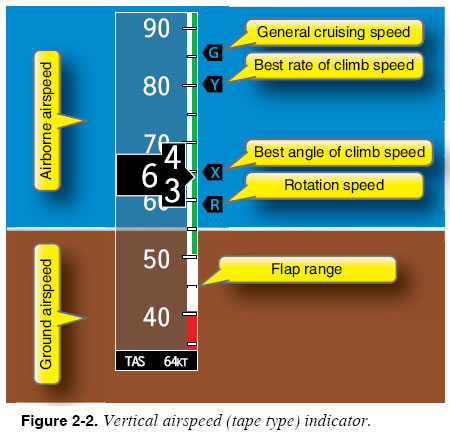
Enhancements to the Primary Flight Instruments Some PFDs offer enhancements to the primary flight instruments. Figure 2-2 shows an airspeed indicator that displays reference speeds (V-speeds) and operating ranges for the aircraft. Operating ranges are depicted using familiar color coding on the airspeed indicator. One negative human factor concerning this type of presentation should be remembered: while most of the displays are intuitive in that a high indication (such as climb pitch or vertical speed) is corrected by lowering the nose of the aircraft, the situation with the usual airspeed vertical tape is the opposite. In most current displays, the lower speeds are at the lower side of the airspeed indicator, while the upper or higher speeds are in the top portion of the airspeed display area. Therefore, if a low airspeed is indicated, you must lower the nose of the aircraft to increase, which is counterintuitive to the other indications.
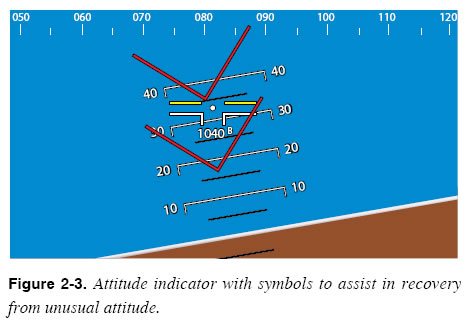
Figure 2-3 shows an attitude indicator that presents red symbols to assist in recovery from unusual attitudes. The symbols on the display recommend a lower pitch attitude.
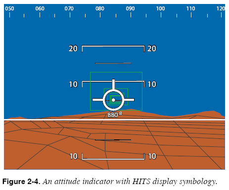
Other valuable enhancements include trend indicators, which process data to predict and display future performance. For example, some systems generate “trend vectors” that predict the aircraft’s airspeed, altitude, and bank angle up to several seconds into the future. Primary Flight Instrument Systems The primary flight instruments that appear on a PFD are driven by instrument sensor systems that are more sophisticated than conventional instrument systems. The attitude of the aircraft may be measured using microelectronic sensors that are more sensitive and reliable than traditional gyroscopic instruments. These sensors measure pitch, roll, and yaw movements away from a known reference attitude. Aircraft heading may be determined using a magnetic direction-sensing device such as a magnetometer or a magnetic flux valve. Attitude and heading systems are typically bundled together as an attitude heading reference system (AHRS), which contains not only the sensors used to measure attitude and heading, but also a computer that accepts sensor inputs and performs calculations. Some AHRSs must be initialized on the ground prior to departure. The initialization procedure allows the system to establish a reference attitude used as a benchmark for all future attitude changes. As in any navigation system, attitude heading reference systems accumulate error over time. For this reason, AHRSs continually correct themselves, using periods of stable flight to make small corrections to the reference attitude. The system’s ability to correct itself can be diminished during prolonged periods of turbulence. Some AHRSs can be reinitialized in flight, while others cannot. The pilot must become familiar with the operating procedures and capabilities of a particular system. Information on altitude and airspeed is provided by sensors that measure static and ram air pressure. An air data computer (ADC) combines those air pressure and temperature sensors with a computer processor that is capable of calculating pressure altitude, indicated airspeed, vertical speed, and true airspeed. An air data attitude heading reference system (ADAHRS) combines all of the systems previously described into one integrated unit. Navigation Instruments PFDs and multi-function displays (MFDs) typically combine several navigation instruments into a single presentation. The instrument appearing at the bottom of the PFD in Figure 2-1 contains two navigation indicators: a course deviation indicator and a bearing pointer. These instruments can be displayed in a variety of views, and can be coupled to many of the navigation receivers (e.g., instrument landing system (ILS), global positioning system (GPS), very high frequency (VHF) omnidirectional range (VOR)) available in the aircraft. The pilot must, therefore, be sure to maintain an awareness of which navigation receivers are coupled to each navigation indicator. MFDs may provide the same type of display as installed in the PFD position, but are usually programmed to display just the navigation information with traffic, systems data, radar Stormscope®/ Strikefinder®. However, in many systems, the MFD can be selected to repeat the information presented on the PFD, thereby becoming the standby PFD. The pilot should be absolutely certain of and proficient with the standby modes of operation. More sophisticated PFDs present three-dimensional (3D) course indications. The primary flight display in Figure 2-4 shows a 3D course indication, called a highway-in-the-sky (HITS) display. This display provides both lateral and vertical guidance along the planned flight path, while simultaneously presenting a 3D picture of the surrounding terrain. Keeping the symbolic aircraft within the green boxes on the display ensures that the flight remains within the selected GPS route and altitude. Consult the AFM and avionics manual for required navigational configuration for this function to be available.
|
| ©AvStop Online Magazine Contact Us Return To Books |