![]()
|
|
||
| CHAPTER 2. Electronic Flight Instruments
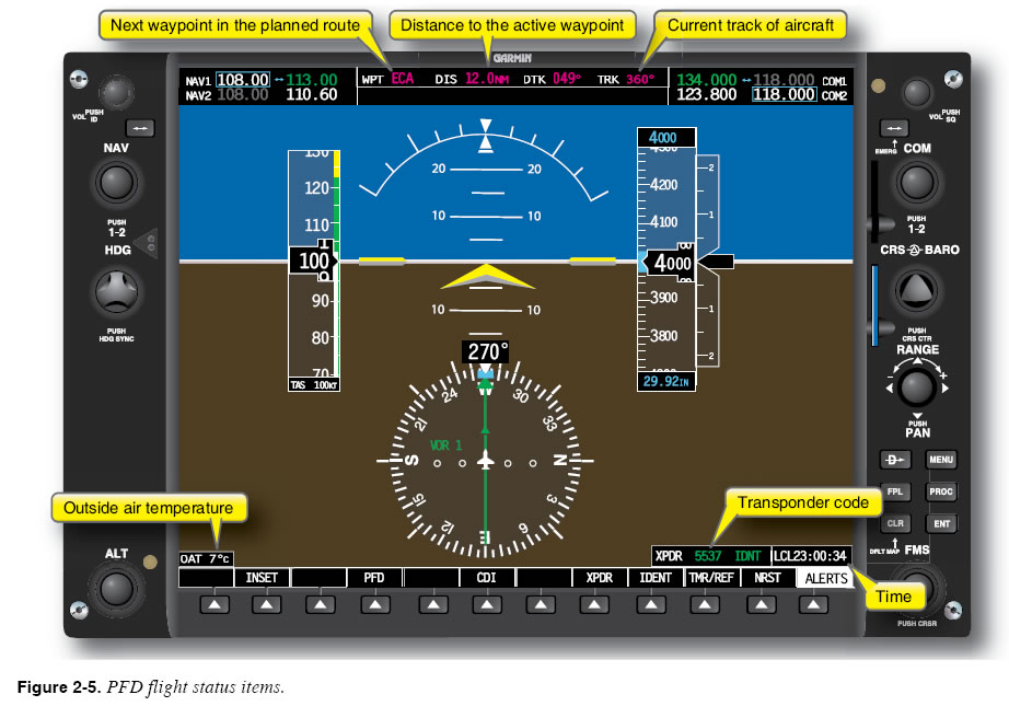
Other Flight Status Information An important feature of the PFD is its ability to gather information from other aircraft systems and present it to the pilot in the integrated display. For example, the PFD in Figure 2-5 presents many useful items about the status of the flight. The top bar shows the next waypoint in the planned flight route, the distance and bearing to the waypoint, and the current ground track. The outside air temperature (OAT) is shown in the lower left corner of the display. The transponder code and status are shown with the current time in the lower right corner. This PFD also allows the pilot to tune and identify communication and navigation radio frequencies at the top of the display.
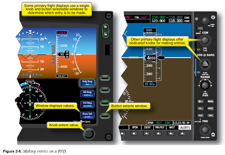
Making Entries on the PFD PFDs have evolved and have become more than flight displays in many cases. The amount of data available for display can overwhelm the pilot with data. Therefore, many manufacturers have integrated data control and display controls into the display unit itself, usually around the perimeter of the unit. These data and display controls provide different ways of selecting necessary information, such as altimeter settings, radials, and courses. Figure 2-6 illustrates two different kinds of controls for making entries on primary flight displays. Some PFDs utilize a single knob and button-selectable windows to determine which entry is to be made. Other PFDs offer dedicated knobs for making entries; quantities are sometimes entered in one location and displayed in another. Still other units retain all controls on a separate control panel in the console or on the instrument panel.
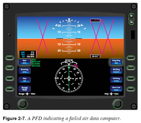
Failures and the Primary Flight Display Instrument System Failure The competent pilot is familiar with the behavior of each instrument system when failures occur, and is able to recognize failure indications when they appear on the primary flight display. Manufacturers typically use a bold red “X” over, or in place of, the inoperative instruments and provide annunciator messages about failed systems. It is the pilot’s job to interpret how this information impacts the flight. The inoperative airspeed, altitude, and vertical speed indicators on the PFD in Figure 2-7 indicate the failure of the air data computer. As do all electronic flight displays, navigation units (area navigation (RNAV)/flight management systems (FMS)) and instrumentation sensors rely on steady, uninterrupted power sources of 24 VDC or 12 VDC power. Any interruptions in the power supplies, such as alternator/ regulator failure, drive belt failure, lightning strikes, wiring harness problems, or other electrical failures, can completely disrupt the systems, leading to erratic indications or completely inoperative units. Especially in standard category aircraft not designed or built with the redundancy inherent in transport category aircraft, a proficient and prudent pilot plans for failures and has alternate plans and procedures readily available.
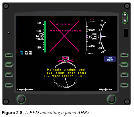
The inoperative attitude indicator on the PFD in Figure 2-8 indicates the failure of the AHRS. By understanding which flight instruments are supported by which underlying systems (e.g., ADC, attitude heading reference system (AHRS)), you can quickly understand the source of a failure. It is important to be thoroughly familiar with the operation of the systems and the abnormal/emergency procedures in the pilot’s operating handbook (POH), aircraft flight manual (AFM), or avionics guides.
|
| ©AvStop Online Magazine Contact Us Return To Books |