![]()
|
|
||
| CHAPTER 3. Navigation
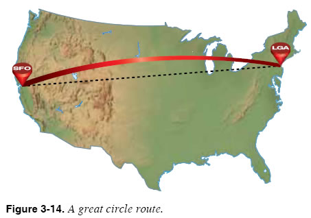
Check the Desired Tracks On the flight planning page, you can also see the course that the computer has calculated between waypoints along the route. A desired track between two waypoints represents the shortest path between them. The desired track between two waypoints may differ from the course seen on the aeronautical charts. In fact, there may be a difference of several degrees between the desired track and the airway course. Some of this difference may be due to the method in which the FMS accounts for magnetic variation. Some units use an internal database and interpolate, while others compute all values from tables. Unlike the world as printed on paper charts, the earth is round, not flat. The shortest distance between two points on the earth is not a straight line; it is an arc, as shown in Figure 3-14.
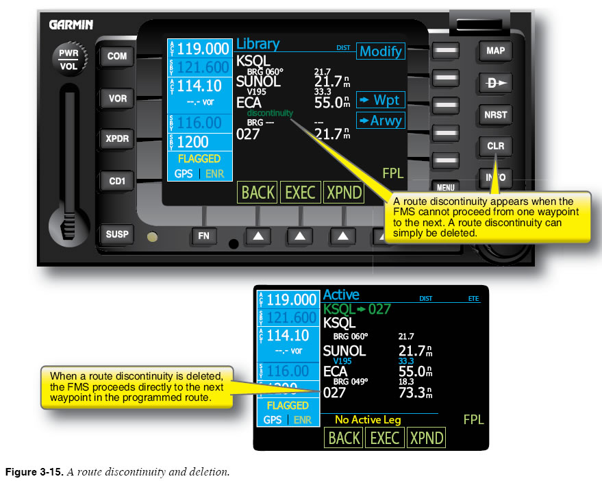
The shortest route between two points on the surface of the earth is called a great circle route. To find the great circle route that connects two points, imagine a geometric plane cutting through the earth that passes through the two points and the center of the earth. On the great circle route from SFO to LGA in Figure 3-14, departing SFO, the desired track is a little less than 90 degrees. Upon arrival at LGA, it appears to be greater than 90 degrees. The desired track heading is constantly changing since it is a circle, not a line. If, however, the difference exceeds several degrees, you need to investigate further to determine the cause. Check for Route Discontinuities Some FMS units do not automatically assume that you wish to fly between each of the waypoints that have been entered into the flight plan. When there is a question about how to proceed from one waypoint or instrument procedure to the next, some units insert a “discontinuity” in the programmed route. A route discontinuity indicates that the FMS needs further input from you about how two route segments should be connected. A route discontinuity is shown in Figure 3-15. If you wish to proceed directly from the waypoint that appears before the route discontinuity to the waypoint that appears after, you can simply delete the discontinuity, as shown in Figure 3-15.
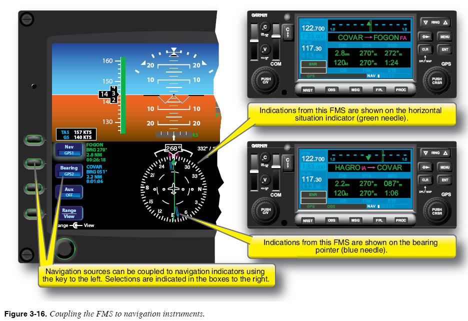
If the route discontinuity is left in the flight plan, the unit computer will not provide guidance beyond the waypoint that occurs before the discontinuity. Maintaining Proficiency: Aeronautical Knowledge It is easy to use an FMS without performing your own calculations for courses, headings, times, distances, and fuel used, but studies have demonstrated that aeronautical skills that are not practiced regularly quickly fade, regardless of experience level or certificates and ratings held. Abnormal and emergency situations (e.g., electrical failure) do occur, so it is important to maintain proficiency in at least making “rule of thumb” calculations on your own. Coupling the FMS to the Navigation Indicator(s) Every advanced avionics cockpit features one or more navigation instruments used for course guidance. The navigation indicator (e.g., a horizontal situation indicator (HSI) or electronic HSI) may include one or more course deviation indicators (CDIs), as well as one or more radio magnetic indicators (RMIs). When automatic course/ en route/ approach tracking is desired, you must couple (or connect) the FMS to the autopilot and select “navigation” as the source for the autopilot versus “heading” source, for example. With VOR navigation, that was sufficient. Now, with multiple sources of navigation data available, you must also ensure that the proper navigation information source was selected in the FMS. Every advanced cockpit offers buttons or switches that allow you to choose which navigation indications will be shown on which display or instrument. This situation becomes complicated in aircraft that contain dual FMS/RNAV installations and redundant selectable displays or instruments. The pilot must learn how to configure each navigation instrument to show indications from each possible navigation source. Figure 3-16 shows an example of a primary flight display (PFD) navigation indicator that combines a course deviation indicator (CDI) and a radio magnetic indicator (RMI), and allows the pilot to display indications from one of two FMS on either indicator.
|
| ©AvStop Online Magazine Contact Us Return To Books |