![]()
|
|
||
| CHAPTER 3. Navigation
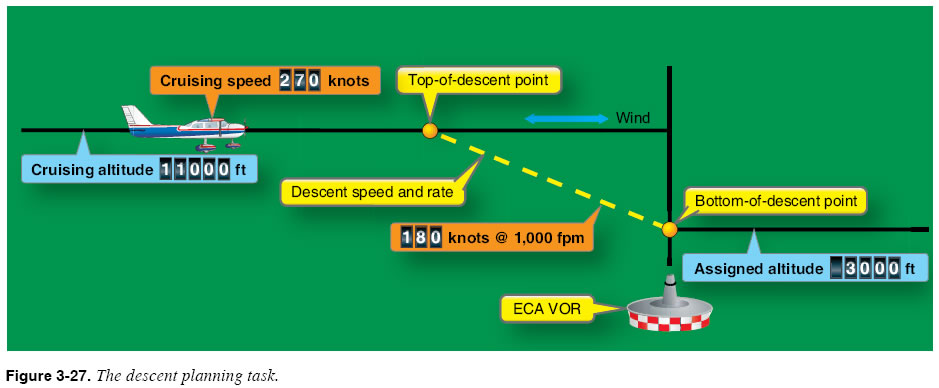
Managing Speed Up to this point the focus has been on the task of losing excess altitude. For example, in the situation shown in Figure 3-27, you are faced with the requirement to reduce altitude from 11,000 feet to 3,000 feet. Most descent scenarios also present the challenge of losing excess speed. In piston aircraft of modest performance, losing excess speed seldom requires much forethought. Slowing from a cruising speed of 120 knots to an approach speed of 100 knots requires little planning and can be accomplished quickly at almost any point during a descent. Flying higher performance aircraft requires a closer look at concepts of excess altitude and excess speed. Higher performance piston engines usually require descent scheduling to prevent engine shock cooling. Either the engines must be cooled gradually before descent, or power must be constant and considerable in the descent to prevent excessive cooling. In such instances, a much longer deceleration and gradual engine cooling must be planned to prevent powerplant damage. Additionally, the turbulence penetration or VA speeds should be considered with respect to weather conditions to avoid high speeds in turbulent conditions, which could result in overstressing the airframe. Drag devices such as spoilers can be of great advantage for such maneuvers. In the scenario in Figure 3-27, a cruising speed of 270 knots is inappropriate as the aircraft descends below 10,000 feet, and even more so as it enters Class C airspace. Therefore, descent planning must include provisions for losing excess airspeed to meet these speed restrictions.
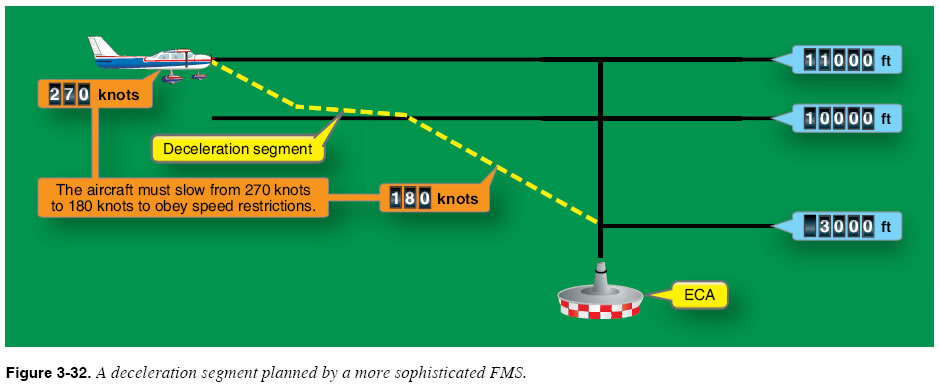
Some sophisticated FMSs are able to build in a deceleration segment that can allow the aircraft to slow from the cruise speed to the desired end-of-descent speed during the descent. This type of navigation system allows you to maintain the cruise speed up until the top-of-descent point and calculates the deceleration simultaneously with the descent. A deceleration segment is illustrated in Figure 3-32.
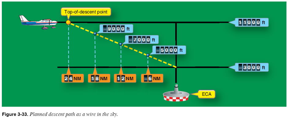
Simple FMS units such as GPS RNAV receivers assume that you will slow the aircraft to the planned descent speed before reaching the top-of-descent point. ATC timing may preclude this plan. Descent Flying Concepts Probably the most important descent flying concept to understand is that a planned descent is basically a “pathway in the sky,” similar to the glideslope associated with an ILS procedure. If you start down at the planned top-of-descent point, fly a groundspeed of 180 knots, and descend at 1,000 feet per minute (fpm), you will be flying on a fixed path between the top-of-descent point and the bottom-of-descent point. If you maintain the 180-knot and 1,000-foot-perminute descent, you will cross a point 18 NM from ECA at exactly 9,000 feet, a point 12 NM from ECA at 7,000 feet, and a point 6 NM from ECA at exactly 5,000 feet, as shown in Figure 3-33.
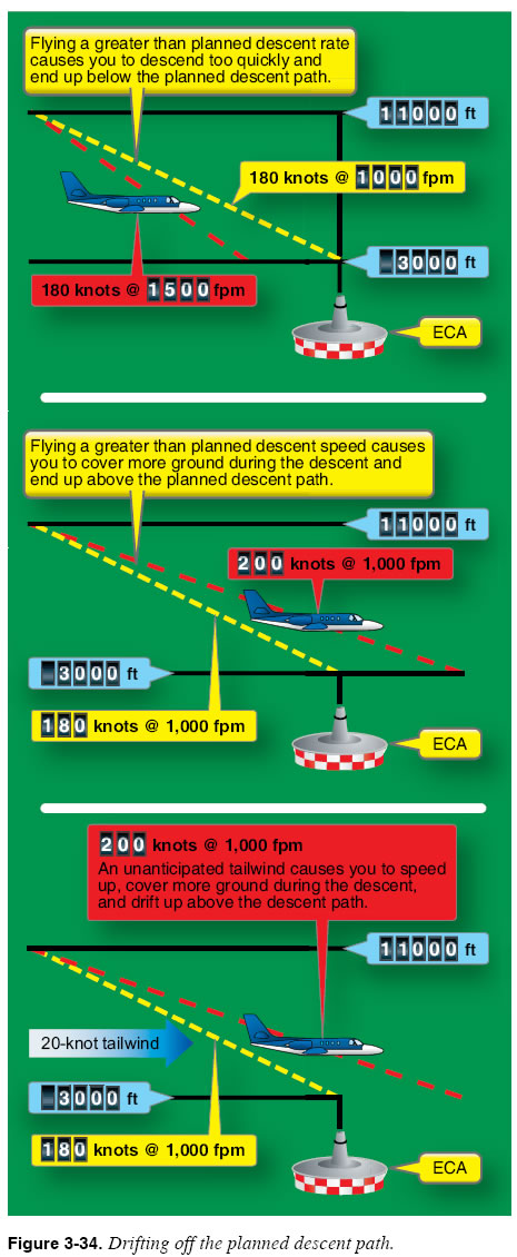
If you are at a different altitude at any of these points, you will not cross ECA at the required 3,000 feet unless corrective action is taken. Four things can cause you to drift from a planned descent path:
Figure 3-34 shows the effect of each situation on the position of the aircraft with respect to the planned descent path.
|
| ©AvStop Online Magazine Contact Us Return To Books |