![]()
|
|
||
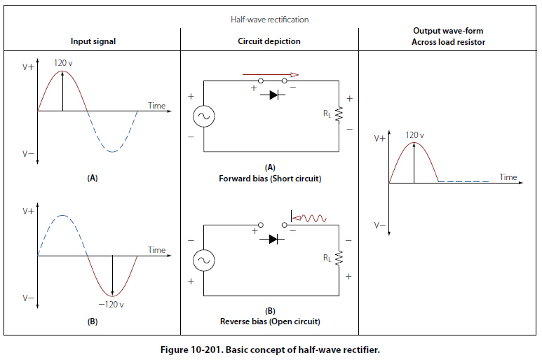
Half-Wave Rectifier Figure 10-201 illustrates the basic concept of a halfwave rectifier. When an AC signal is on a positive swing as shown in illustration A of the input signal, the polarities across the diode and the load resistor will also be positive. In this case, the diode is forward biased and can be replaced with a short circuit as shown in the illustration. The positive portion of the input signal will then appear across the load resistor with no loss in potential across the series diode.
Illustration B now shows the input signal being reversed. Note that the polarities across the diode and the load resistor are also reversed. In this case, the diode is now reverse biased and can be replaced with an equivalent open circuit. The current in the circuit is now 0 amperes and the voltage drop over the load resistor is 0 volts. The resulting waveform for a complete sinusoidal input can be seen at the far right of Figure 10-201. The output waveform is a reproduction of the input waveform minus the negative voltage swing of the wave. For this reason, this type of rectifier is called a half-wave rectifier. |
| ©AvStop Online Magazine Contact Us Return To Books |