![]()
|
|
||
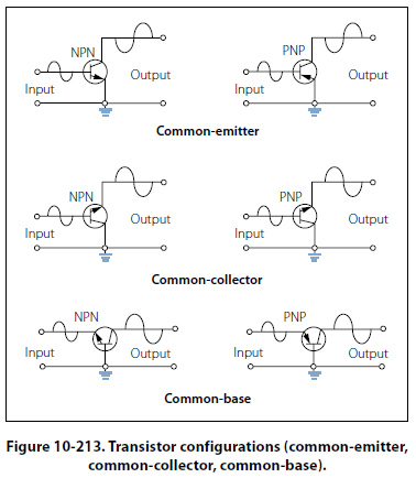
Common-Collector Configuration This transistor configuration is usually used for impedance matching. It is also used as a current driver due to its high current gain. It is also very useful in switching circuits since it has the ability to pass signals in either direction. [Figure 10-213]
In the common-collector circuit, the input signal is applied to the base, and the output signal is taken from the emitter, leaving the collector as the common point between the input and the output. The input resistance of the CC circuit is high, while the output resistance is low. The current gain is higher than that in the common- emitter, but it has a lower power gain than either the common-emitter or common-base configuration. Just like the common-base configuration, the output signal of the common-collector circuit is in phase with the input signal. The common-collector is typically referred to as an emitter-follower because the output developed on the emitter follows the input signal applied to the base. Common-Base Configuration The primary use of this configuration is for impedance matching because it has low input impedance and high output resistance. Two factors, however, limit the usefulness of this circuit application. First is the low input resistance and second is its lack of current, which is always below 1. Since the CB configuration will give voltage amplification, there are some applications for this circuit, such as microphone amplifiers. [Figure 10-213] In the common-base circuit, the input signal is applied to the emitter and the output signal is taken from the collector. In this case, both the input and the output have the base as a common element. When an input signal is applied to the emitter, it causes the emitterbase junction to react in the same manner as that in the common-emitter circuit. When an input adds to the bias, it will increase the transistor current; conversely, when the signal opposes the bias, the current in the transistor decreases. The signal adds to the forward bias, since it is applied to the emitter, causing the collector current to increase. This increase in IC results in a greater voltage drop across the load resistor RL, thus lowering the collector voltage EC. The collector voltage, in becoming less negative, will swing in a positive direction and is therefore in phase with the incoming positive signal. Vacuum Tubes The use of vacuum tubes in aircraft electrical and electronic systems has rapidly declined due to the many advantages of using transistors. However, some systems still employ vacuum tubes in special applications, and possibly some older model aircraft still in service are equipped with devices that use vacuum tubes. While these components may still be in service, their infrequent occurrence does not warrant a detailed discussion. Originally, vacuum tubes were developed for radio work. They are used in radio transmitters as amplifiers for controlling voltage and current, as oscillators for generating audio and radio frequency signals, and as rectifiers for converting alternating current into direct current. While there are many types of vacuum tubes for a variety of applications, the most common types fall into one of the following families: (1) diode, (2) triode, (3) tetrode, and (4) pentode. Each of these vacuum tube types operates on the following fundamental principles. When a piece of metal is heated, the speed of the electrons in the metal is increased. If the metal is heated to a high enough temperature, the electrons are accelerated to the point where some of them actually leave the surface of the metal. In a vacuum tube, electrons are supplied by a piece of metal called a cathode, which is heated by an electric current. Within limits, the hotter the cathode, the greater the number of electrons it will give off or emit. To increase the number of electrons emitted, the cathode is usually coated with special chemical compounds. If an external field does not draw the emitted electrons away, they form about the cathode into a negatively charged cloud called the space charge. The accumulation of negative electrons near the emitter repels others coming from the emitter. The emitter, if insulated, becomes positive because of the loss of electrons. This establishes an electrostatic field between the cloud of negative electrons and the now positive cathode. A balance is reached when only enough electrons flow from the cathode to the area surrounding it to supply the loss caused by diffusion of the space charge. |
| ©AvStop Online Magazine Contact Us Return To Books |