![]()
|
|
||
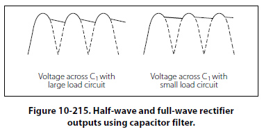
Filtering One of the more common uses of the capacitor and inductor that the technician may find in the field is that of the filter. Filtering Characteristics of Capacitors The nature of capacitance opposes a voltage change across its terminal by storing energy in its electrostatic field. Whenever the voltage tends to rise, the capacitor converts this voltage change to stored energy. When the voltage tends to fall, the capacitor converts this stored energy back to voltage. The use of a capacitor for filtering the output of a rectifier is illustrated in Figure 10- 214. The rectifier is shown as a block, and the capacitor C1 is connected in parallel with the load R1. The capacitor C1 is chosen to offer very low impedance to the AC ripple frequency and very high impedance to the DC component. The ripple voltage is therefore bypassed to ground through the low impedance path of the capacitor, while the DC voltage is applied unchanged to the load. The effect of the capacitor on the output of the rectifier can be seen in the waveshapes shown in Figure 10-215. Dotted lines show the rectifier output, while the solid lines show the effect of the capacitor. In this example, full-wave rectifier outputs are shown. The capacitor C1 charges when the rectifier voltage output tends to increase and discharges when the voltage output tends to decrease. In this manner, the voltage across the load R1 is kept fairly constant.
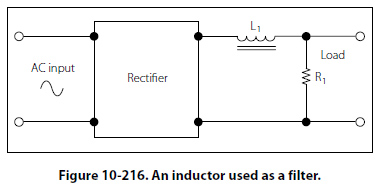
Filtering Characteristics of Inductors The inductance provided by an inductor may be used as a filter, because it opposes a change in current through it by storing energy in its electromagnetic field. Whenever the current increases, the stored energy in the electromagnetic field increases. When the current through the inductor decreases, the inductor supplies the energy back into the circuit in order to maintain the existing flow of current. The use of an inductor for filtering the output of a rectifier is shown in Figure 10-216. Note that in this network the inductor L1 is in series with the load R1.
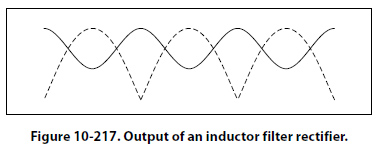
The inductance L1 is selected to offer high impedance to the AC ripple voltage and low impedance to the DC component. The result is a very large voltage drop across the inductor and a very small voltage drop across the load R1. For the DC component, however, a very small voltage drop occurs across the inductor and a very large voltage drop across the load. The effect of an inductor on the output of a full-wave rectifier in the output waveshape is shown in Figure 10-217.
|
| ©AvStop Online Magazine Contact Us Return To Books |