![]()
|
|
||
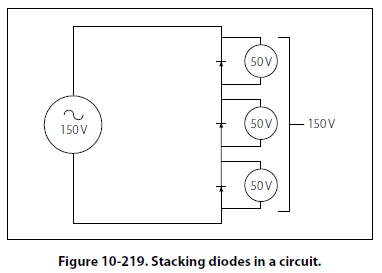
Common Filter Configurations Capacitors and inductors are combined in various ways to provide more satisfactory filtering than can be obtained with a single capacitor or inductor. These are referred to collectively as “LC filters." Several combinations are shown schematically in Figure 10-218. Note that the L, or inverted L-type, and the T-type filter sections resemble schematically the corresponding letters of the alphabet. The pi-type filter section resembles the Greek letter pi (∏) schematically. All the filter sections shown are similar in that the inductances are in series and the capacitances are in parallel with the load. The inductances must, therefore, offer very high impedance and the capacitors very low impedance to the ripple frequency. Since the ripple frequency is comparatively low, the inductances are iron core coils having large values of inductance (several henries). Because they offer such high impedance to the ripple frequency, these coils are called chokes. The capacitors must also be large (several microfarads) to offer very little opposition to the ripple frequency. Because the voltage across the capacitor is DC, electrolytic capacitors are frequently used as filter capacitors. Always observe the correct polarity in connecting electrolytic capacitors. LC filters are also classified according to the position of the capacitor and inductor. A capacitor input filter is one in which the capacitor is connected directly across the output terminals of the rectifier. A choke input filter is one in which a choke precedes the filter capacitor. If it is necessary to increase the applied voltage to more than a single rectifier can tolerate, the usual solution is to stack them. These rectifiers are similar to resistors added in series. Each resistor will drop a portion of the applied voltage rather than the total voltage. The same theory applies to rectifiers added in series, or stacked. Series stacking increases the voltage rating. If, for example, a rectifier will be destroyed with an applied voltage exceeding 50 volts, and it is to be used in a circuit with an applied voltage of 150 volts, stacking of diodes can be employed. The result is shown in Figure 10-219.
Basic LC Filters Analog filters are circuits that perform signal processing functions, specifically intended to remove unwanted signal components such as ripple and enhance desired signals. The simplest analog filters are based on combinations of inductors and capacitors. The four basic categories of filters discussed are: low-pass, high-pass, band-pass and band-stop. All these types are collectively known as passive filters, because they do not depend on any external power source. The operation of a filter relies on the characteristic of variable inductive and capacitive reactance based on the applied frequency. In review, the inductor will block high-frequency signals (high reactance) and conduct low-frequency signals (low reactance), while capacitors do the reverse. A filter in which the signal passes through an inductor, or in which a capacitor provides a path to earth, presents less attenuation (reduction) to a low-frequency signal than to a high-frequency signal and is considered a low-pass filter. If the signal passes through a capacitor, or has a path to ground through an inductor, then the filter presents less attenuation to high-frequency signals than low-frequency signals and is then considered a high-pass filter. Typically after an AC signal is rectified the pulses of voltage are changed to usable form of DC by way of filtering. |
| ©AvStop Online Magazine Contact Us Return To Books |