![]()
|
|
||
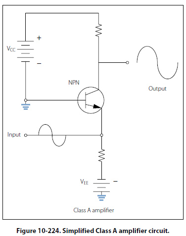
Amplifier Circuits An amplifier is a device that enables an input signal to control an output signal. The output signal will have some or all of the characteristics of the input signal but will generally be a greater magnitude than the input signal in terms of voltage, current, or power. Gain is the basic function of all amplifiers. Because of this gain, we can expect the output signal to be greater than the input signal. If for example we have an input signal of 1 volt and an output signal of 10 volts, then the gain factor can be determined by: Gain = Signal out /Signal in Voltage gain is usually used to describe the operation of a small gain amplifier. In this type of an amplifier, the output signal voltage is larger than the input signal voltage. Power gain, on the other hand, is usually used to describe the operation of large signal amplifiers. In the case of power gain amplifiers, the gain is not based on voltage but on watts. A power amplifier is an amplifier in which the output signal power is greater than the input signal power. Most power amplifiers are used as the final stage of amplification and drive the output device. The output device could be a cockpit or cabin speaker, an indicator, or antenna. Whatever the device, the power to make it work comes from the final stage of amplification. Drivers for autopilot servos are sometimes contained in line replaceable units (LRUs) called autopilot amplifiers. These units take the low signal commands from the flight guidance system and amplify the signals to a level usable for driving the servo motors. Classification The classification of a transistor amplifier circuit is determined by the percentage of the time that the current flows through the output circuit in relation to the input signal. There are four classifications of operation: A, AB, B, and C. Each class of operation has a certain use and characteristic. No individual class of amplifiers is considered the “best." The best use of an amplifier is a matter of proper selection for the particular operation desired. Class A Figure 10-224, shows a simplified Class A amplifier circuit. In the Class A operation, the current in the transistor flows for 100 percent or 360° of the input signal. Class A operation is the least efficient class of operation but provides the best fidelity. Fidelity simply means that the output signal is a good reproduction of the input signal in all respects other than the amplitude,
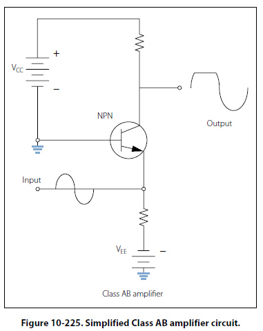
which is amplified. In some cases, there may be some phase shifting between the input signal and the output signal. Typically, the phase difference is 180°. If the output signal is not a good reproduction of the input signal, then the signal is said to be distorted. Distortion is any undesired change to the signal from the input to the output. The efficiency of an amplifier refers to the amount of power delivered to the output compared to the power supplied to the circuit. Every device in the circuit consumes power in order to operate. If the amplifier operates for 360° of input signal, then it is using more power than if it was using only 180° of input signal. The more power consumed by the amplifier, the less there is available for the output signal. Usually the Class A amplifier is used where efficiency is of little concern and where fidelity in reproduction is desired. Class AB Figure 10-225, shows a simplified Class AB amplifier circuit. In the Class AB operation, the transistor current flows for more than 50 percent but less than 100 percent of the input signal. Unlike the Class A amplifier, the output signal is distorted. A portion of the output circuit appears to be truncated. This is due to the lack of current through the transistor during this point of operation. When the emitter in this case becomes positive enough, the transistor cannot conduct because the
base to emitter junction is no longer forward biased. The input signal going positive beyond this point will not produce any further output and the output will remain level. The Class AB amplifier has a better efficiency and a poorer fidelity than the Class A amplifier. These amplifiers are used when an exact reproduction of the input is not required but both the positive and negative portions of the input signals need to be available on the output. |
| ©AvStop Online Magazine Contact Us Return To Books |