![]()
|
|
||
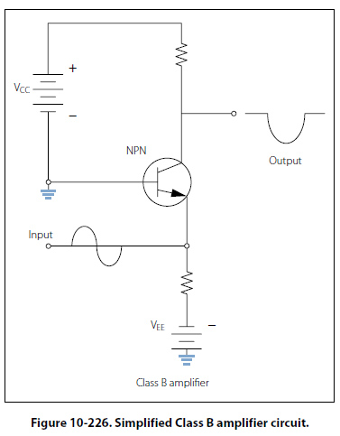
Class B Figure 10-226, shows a simplified Class B amplifier circuit. In Class B operation, the transistor current flows for only 50 percent of the input signal. In this illustration, the base-emitter bias will not allow the transistor to conduct whenever the input signal is greater than zero. In this case, only the negative portion of the input signal will be reproduced. Unlike the rectifier, the Class B amplifier will not only reproduce half of the input signal, but it will also amplify it. Class B amplifiers are twice as efficient as the Class A amplifier because the amplifying device only uses power for half of the input signal.
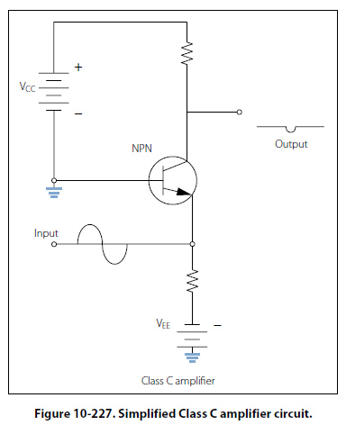
Class C Figure 10-227, shows a simplified Class C amplifier circuit. In Class C operations, transistor current flows for less than 50 percent of the input signal. This class of operation is the most efficient. Because the transistor does not conduct except during a small portion of the input signal, this is the most efficient class of amplifier. The distortion of the Class C amplifier is greater (poor fidelity) than the Class A, AB, and B amplifiers because a small portion of the input signal is reproduced on the output. Class C amplifiers are used when the output signal is used for only small portions of time.
|
| ©AvStop Online Magazine Contact Us Return To Books |