![]()
|
|
||
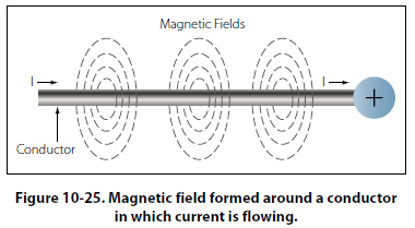
Electromagnetism In 1820, the Danish physicist, Hans Christian Oersted, discovered that the needle of a compass brought near a current carrying conductor would be deflected. When the current flow stopped, the compass needle returned to its original position. This important discovery demonstrated a relationship between electricity and magnetism that led to the electromagnet and to many of the inventions on which modern industry is based. Oersted discovered that the magnetic field had no connection with the conductor in which the electrons were flowing, because the conductor was made of nonmagnetic copper. The electrons moving through the wire created the magnetic field around the conductor. Since a magnetic field accompanies a charged particle, the greater the current flow, and the greater the magnetic field. Figure 10-25 illustrates the magnetic field around
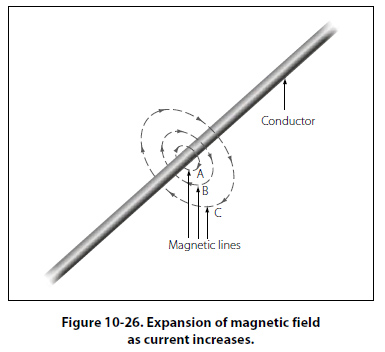
a current carrying wire. A series of concentric circles around the conductor represent the field, which if all the lines were shown would appear more as a continuous cylinder of such circles around the conductor. As long as current flows in the conductor, the lines of force remain around it. [Figure 10-26] If a small current flows through the conductor, there will be a line of force extending out to circle A. If the current flow is increased, the line of force will increase in size to circle B, and a further increase in current will expand it to circle C. As the original line (circle) of force expands from circle A to B, a new line of force will appear at circle A. As the current flow increases, the number of circles of force increases, expanding the outer circles farther from the surface of the current carrying conductor.
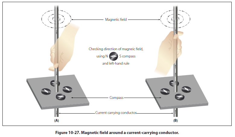
If the current flow is a steady nonvarying direct current, the magnetic field remains stationary. When the current stops, the magnetic field collapses and the magnetism around the conductor disappears. A compass needle is used to demonstrate the direction of the magnetic field around a current carrying conductor. Figure 10-27 View A shows a compass needle positioned at right angles to, and approximately one inch from, a current carrying conductor. If no current were flowing, the north seeking end of the compass needle would point toward the earth’s magnetic pole. When current flows, the needle lines itself up at right angles to a radius drawn from the conductor. Since the compass needle is a small magnet, with lines of force extending from south to north inside the metal, it will turn until the direction of these lines agrees with the direction of the lines of force around the conductor. As
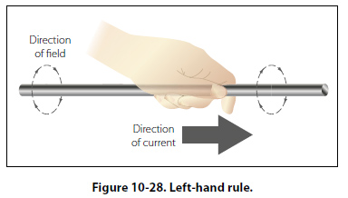
the compass needle is moved around the conductor, it will maintain itself in a position at right angles to the conductor, indicating that the magnetic field around a current carrying conductor is circular. As shown in View B of Figure 10-27, when the direction of current flow through the conductor is reversed, the compass needle will point in the opposite direction, indicating the magnetic field has reversed its direction. A method used to determine the direction of the lines of force when the direction of the current flow is known, is shown in Figure 10-28.
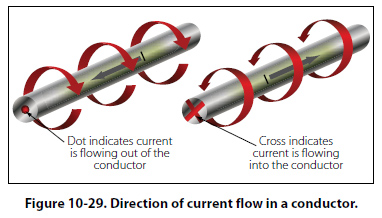
Although it has been stated that the lines of force have direction, this should not be construed to mean that the lines have motion in a circular direction around the conductor. Although the lines of force tend to act in a clockwise or counterclockwise direction, they are not revolving around the conductor. Since current flows from negative to positive, many illustrations indicate current direction with a dot symbol on the end of the conductor when the electrons are flowing toward and a plus sign when the current is flowing away from the observer. [Figure 10-29]
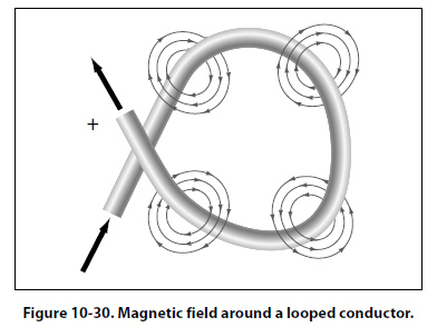
When a wire is bent into a loop and an electric current flows through it, the left-hand rule remains valid. [Figure 10-30]
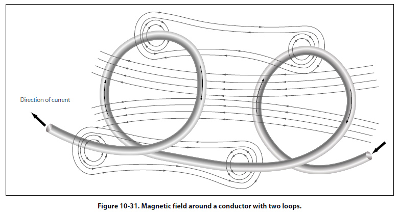
If the wire is coiled into two loops, many of the lines of force become large enough to include both loops. Lines of force go through the loops in the same direction, circle around the outside of the two coils, and come in at the opposite end. [Figure 10-31]
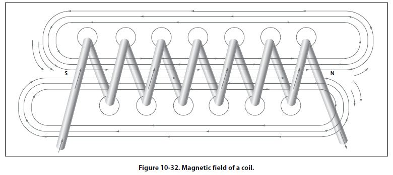
When a wire contains many such loops, it is called a coil. The lines of force form a pattern through all the loops, causing a high concentration of flux lines through the center of the coil. [Figure 10-32]
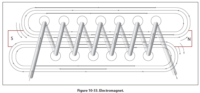
In a coil made from loops of a conductor, many of the lines of force are dissipated between the loops of the coil. By placing a soft iron bar inside the coil, the lines of force will be concentrated in the center of the coil, since soft iron has a greater permeability than air. [Figure 10-33] This combination of an iron core in a coil of
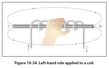
wire loops, or turns, is called an electromagnet, since the poles (ends) of the coil possess the characteristics of a bar magnet. The addition of the soft iron core does two things for the current carrying coil. First, the magnetic flux is increased, and second, the flux lines are more highly concentrated. When direct current flows through the coil, the core will become magnetized with the same polarity (location of north and south poles) as the coil would have without the core. If the current is reversed, the polarity will also be reversed. The polarity of the electromagnet is determined by the left-hand rule in the same manner as the polarity of the coil without the core was determined. If the coil is grasped in the left hand in such a manner that the fingers curve around the coil in the direction of electron flow (minus to plus), the thumb will point in the direction of the north pole. [Figure 10-34]
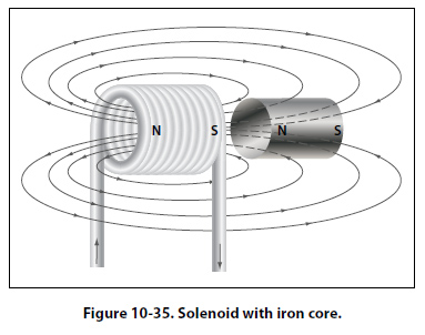
The strength of the magnetic field of the electromagnet can be increased by either increasing the flow of current or the number of loops in the wire. Doubling the current flow approximately doubles the strength of the field, and in a similar manner, doubling the number of loops approximately doubles magnetic field strength. Finally, the type metal in the core is a factor in the field strength of the electromagnet. A soft iron bar is attracted to either pole of a permanent magnet and, likewise, is attracted by a current carrying coil. The lines of force extend through the soft iron, magnetizing it by induction and pulling the iron bar toward the coil. If the bar is free to move, it will be drawn into the coil to a position near the center where the field is strongest. [Figure 10-35]
Electromagnets are used in electrical instruments, motors, generators, relays, and other devices. Some electromagnetic devices operate on the principle that an iron core held away from the center of a coil will be rapidly pulled into a center position when the coil is energized. This principle is used in the solenoid, also called solenoid switch or relay, in which the iron core is spring-loaded off center and moves to complete a circuit when the coil is energized. |
| ©AvStop Online Magazine Contact Us Return To Books |