![]()
|
|
||
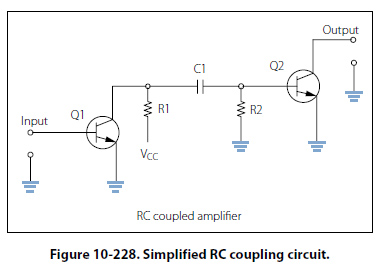
Methods of Coupling Coupling is used to transfer a signal from one stage on an amplifier to another stage. Regardless of whether an amplifier is a single stage or one in a series of stages, there must be a method for the signal to enter and leave the circuit. Coupling is the process of transferring the energy between circuits. There are a number of ways for making this transfer and to discuss these methods in detail goes beyond the scope of this text. However, four methods are listed below with a brief description of their operation. Direct Coupling Direct coupling is the connection of the output of one stage directly to the input of the next stage. Direct coupling provides a good frequency response because no frequency-sensitive components such as capacitors and inductors are used. Yet this method is not used very often due to the complex power supply requirements and the impedance matching problems. RC Coupling and uses a coupling capacitor and signal developing resistors. Figure 10-228, shows a simplified RC coupling circuit. In this circuit, R1 acts as a load resistor for Q1 and develops the output signal for that stage. The capacitor C1 blocks the DC bias signal and passes the AC output signal. R2 then becomes the load over which the passes AC signal is developed as an input to the base of Q2. This arrangement allows for the bias voltage of each stage to be blocked, while the AC signal is passed to the next stage.
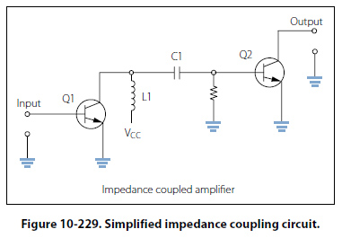
Impedance Coupling Impedance coupling uses a coil as a load for the first stage but otherwise functions just as an RC coupling. Figure 10-229 shows a simplified impedance coupling circuit. This method is similar to the RC coupling method. The difference is that R1 is replaced with inductor L1 as the output load. The amount of signal developed on the output load depends on the inductive reactance of the coil. In order for the inductive reactance to be high, the inductance must be large; the frequency must be high or both. Therefore, load inductors should have relatively large amounts of inductance and are most effective at high frequencies.
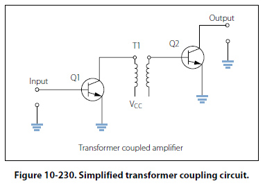
Transformer Coupling Transformer coupling uses a transformer to couple the signal from one stage to the next. Figure 10-230, shows a simplified transformer coupling circuit. The transformer action of T1 couples the signal from the first stage to the second stage. The primary coil of T1 acts as a load for the output of the first stage while the secondary coil acts as the developing impedance for the second stage Q2. Transformer coupling is very efficient and the transformer can aid in impedance matching.
|
| ©AvStop Online Magazine Contact Us Return To Books |