![]()
|
|
||
Applications The number of applications for OP AMPs is too numerous to detail in this text. However, the technician will occasionally come across these devices in modern aircraft and should be able to recognize their general purpose in a circuit. Some of the basic applications are:
Magnetic Amplifiers Magnetic amplifiers do not amplify magnetism but use electromagnetism to amplify a signal. Essentially, the magnetic amplifier is a power amplifier with a very limited frequency response. The frequency range most commonly associated with the magnetic amplifier is 100 hertz and less, which places it in the audio range. As a technical point, the magnetic amplifier is a lowfrequency amplifier. Advantages of the magnetic amplifier are:
Some of the disadvantages of the magnetic amplifier are:
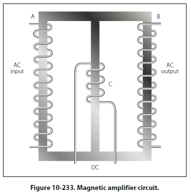
The basic operating principles of the magnetic amplifier are fairly simple. Keep in mind that all amplifiers are current control devices. In this particular case, power that is delivered to the load is controlled by a variable inductance. If an AC voltage is applied to the primary winding of an iron core transformer, the iron core will be magnetized and demagnetized at the same frequency as that of the applied voltage. This, in turn, will induce a voltage in the transformers secondary winding. The output voltage across the terminals of the secondary will depend on the relationship of the number of turns in the primary and the secondary of the transformer. The iron core of the transformer has a saturation point after which the application of a greater magnetic force will produce no change in the intensity of magnetization. Hence, there will be no change in transformer output, even if the input is greatly increased. The magnetic amplifier circuit in Figure 10-233 will be used to explain how a simple magnetic amplifier functions.
The term “amplifier" is used for this arrangement because, by use of a few milliamperes, control of an output of 1 or more amperes is obtained. |
| ©AvStop Online Magazine Contact Us Return To Books |