![]()
|
|
||
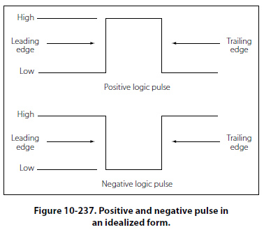
Logic Circuits Logic is considered the science of reasoning — the development of a reasonable conclusion based on known information. Human reasoning tells us that certain propositions are true if certain conditions or premises are true. An annunciator being lit in the master warning panel is an example of a proposition, which is either true or false. For example, predetermined and designed conditions must be met in order for an annunciator in a master warning panel to be lit. A “LOW HYDRAULIC PRESS" annunciator may have a simple set of conditions that will cause it to be illuminated. If the conditions are met, such as a hydraulic reservoir that is low on fluid, causing the line press to be low, then the logic is true and the annunciator will light. Several propositions, when combined will form a logical function. In the example above, the “LOW HYDRAULIC PRESS" annunciator will be on if the LED is not burned out AND the hydraulic press is low OR if the LED is not burned out AND the annunciator test is being asserted. This section on logic circuits only serves as an introduction to the basic concepts. The technician will encounter many situations or problems in everyday life that can be expressed in some form of a logical function. Many problems and situations can be condensed down to simple yes/no or true/false statements, which if logically ordered can filter a problem down to a reasonable answer. The digital logic circuits are well suited for this task and have been employed in today’s integrated circuits found in virtually all of the devices that we take for granted in modern aircraft. These logical circuits are used to carry out the logical functions for such things as navigation and communications. There are several fundamental elements that form the building blocks of the complex digital systems found in line replaceable units (LRUs) and avionics card cages. The following is a very basic outline of what those elements are and what logic conditions they will process. It is far beyond the scope of this text to cover digital logic systems due to the vast body of knowledge that it represents. However, this serves as an introduction and in some limited cases will be useful in reading system block diagrams that use logic symbols to aid the technician in understanding how a given circuit operates. Logic Polarity Electrical pulses can represent two logic conditions and any two differing voltages can be used for this purpose. For example, a positive voltage pulse could represent a true or 1 condition and a negative voltage pulse could then represent a false or 0 logic condition. The condition in which the voltage changes to represent a true or 1 logic is known as the logic polarity. Logic circuits are usually divided into two broad classes known as positive and negative polarity. The voltage levels used and a statement indicating the use of positive or negative logic will usually be specified in the logic diagrams provided by the original equipment manufacturers (OEMs). Positive When a signal that activates a circuit to a 1, true or high condition, has an electrical level that is relatively more positive that the other stated, then the logic polarity is said to be positive. An example would be: Active State: 1 or True = +5 VDC Negative When the signal that actives a circuit to a 1, true or high condition, has an electrical level that is relatively more negative than the other stated, then the logic polarity is said to be negative. An example would be: Active State: 1 or True = 0 VDC Pulse Structure Figure 10-237 illustrates the positive and negative pulse in an idealized form. In both forms, the pulse is
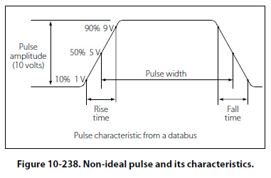
composed of two edges — one being the leading edge and the other the trailing edge. In the case of the positive pulse logic, the positive transition from a lower state to a higher state is the leading edge and the trailing edge is the opposite. In the case of the negative logic pulse, the negative transition from a higher state to a lower state is the leading edge while the rise from the lower state back to the higher state is the trailing edge. Figure 10-237 is considered an ideal pulse because the rise and fall times are instantaneous. In reality, these changes take time, although in actual practice, the rise and fall can be assumed as instantaneous. Figure 10-238 shows the non-ideal pulse and its characteristics. The time required for a pulse to go from a low state to a high state is called the rise time, and the time required for the pulse to return to zero is called the fall time. It is common practice to measure the rise and fall time between 10 percent amplitude and 90 percent amplitude. The reason for taking the measurements in these points is due to the non-linear shape of the pulse in the first 10 percent and final 90 percent of the rise and fall amplitudes. The pulse width is defined as the duration of the pulse. To be more specific, it is the time between the 50 percent amplitude point on both the pulse rise and fall.
|
| ©AvStop Online Magazine Contact Us Return To Books |