![]()
|
|
||
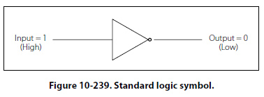
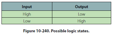
Basic Logic Circuits Boolean logic is a symbolic system used in representing the truth value of statements. It is employed in the binary system used by digital computers primarily because the only truth values (true and false) can be represented by the binary digits 1 and 0. A circuit in computer memory can be open or closed, depending on the value assigned to it. The fundamental operations of Boolean logic, often called Boolean operators, are “and," “or," and “not"; combinations of these make up 13 other Boolean operators. Six of these operators are discussed. The Inverter Logic The inverter circuit performs a basic logic function called inversion. The purpose of the inverter is to convert one logic state into the opposite state. In terms of a binary digit, this would be like converting a 1 to a 0 or a 0 to a 1. When a high voltage is applied to the inverter input, low voltage will be the output. When a low voltage is applied to the input, a high voltage will be on the output. This operation can be put into what is known as a logic or truth table. Figure 10-240 shows the possible logic states for this gate. The standard logic symbol is shown in Figure 10-239. This is the common symbol for an amplifier with a small circle on the output. This type of logic can also be considered a NOT gate.
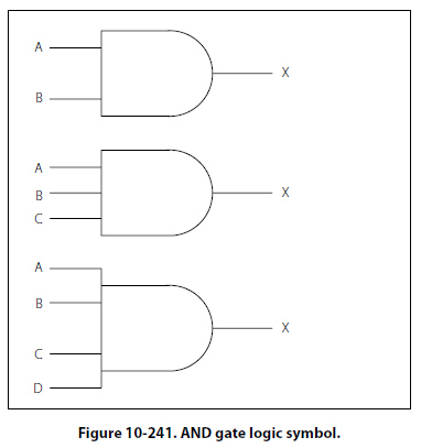
The AND Gate The AND gate is made up of two or more inputs and a single output. The logic symbol is shown in Figure 10-241.
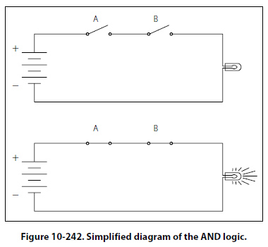
Inputs are on the left and the output is on the right in each of the depictions. Gates with two, three, and four inputs are shown; however, any number of inputs can be used in the AND logic as long as the number is greater than one. The operation of the AND gate is such that the output is high only when all of the inputs are high. If any of the inputs are low, the output will also be low. Therefore, the basic purpose of an AND gate is to determine when certain conditions have been met at the same time. A high level on all inputs will produce a high level on the output. Figure 10-242 shows a simplified diagram of the AND logic with two switches and a light bulb.
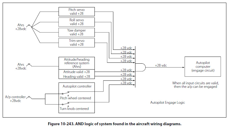
Notice that both switches need to be closed in order for the light bulb to turn on. Any other combination of switch positions will be an open circuit and the light will not turn on. An example of AND logic could possibly be engage logic, found in an autopilot. In this case, the autopilot would not be allowed to be engaged unless certain conditions are first met. Such conditions could be: Vertical gyro is valid AND directional gyro is valid AND all autopilot control knobs are in detents AND servo circuits are operational. Only when these conditions are met will the autopilot be engaged. Figure 10-243 shows the logic of this system found in the aircraft wiring diagrams.
|
| ©AvStop Online Magazine Contact Us Return To Books |