![]()
|
|
||
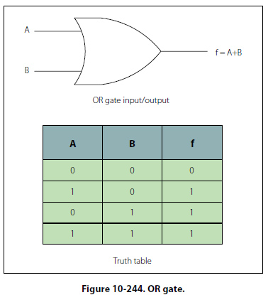
The OR Gate The OR gate has two or more inputs and one output, and is normally represented by the standard logic symbol and truth table as shown in Figure 10-244. In this Figure, notice that the OR gate can have any number of inputs as long as it is greater than one.
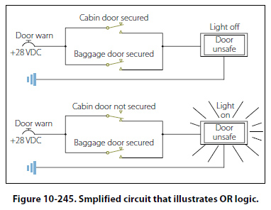
The operation of the OR gate is such that a high on any one of the inputs will produce a high on the output. The only time that a low is produced on the output is if there are no high levels on any input. Figure 10-245
is a simplified circuit that illustrates the OR logic. The example used is a “DOOR UNSAFE" annunciator. Let’s say in this case that the plane has one cabin door and a baggage door. In order for the annunciator light on the master warning panel to extinguish, both doors must be closed and locked. If any one of the doors is not secured properly, the baggage door OR the cabin door, then the “DOOR UNSAFE" annunciator will illuminate. In this case, two switches are in parallel with each other. If either one of the two switches is closed, the light bulb will light up. The lamp will be off only when both switches are open. |
| ©AvStop Online Magazine Contact Us Return To Books |