![]()
|
|
||
Microprocessors The microprocessor is a device that can be programmed to perform arithmetic and logical operations and other functions in a preordered sequence. The microprocessor is usually used as the central processing unit (CPU) in today’s computer systems when it is connected to other components, such as memory chips and input/ output circuits. The basic arrangement and design of the circuits residing in the microprocessor is called the architecture. DC Generators Theory of Operation In the study of alternating current, basic generator principles were introduced to explain the generation of an AC voltage by a coil rotating in a magnetic field. Since this is the basis for all generator operation, it is necessary to review the principles of generation of electrical energy. When lines of magnetic force are cut by a conductor passing through them, voltage is induced in the conductor. The strength of the induced voltage is dependent upon the speed of the conductor and the strength of the magnetic field. If the ends of the conductor are connected to form a complete circuit, a current is induced in the conductor. The conductor and the magnetic field make up an elementary generator.
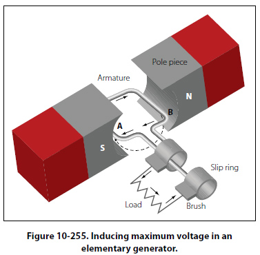
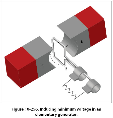
This simple generator is illustrated in Figure 10-255, together with the components of an external generator circuit which collect and use the energy produced by the simple generator. The loop of wire (A and B of Figure 10-255) is arranged to rotate in a magnetic field. When the plane of the loop of wire is parallel to the magnetic lines of force, the voltage induced in the loop causes a current to flow in the direction indicated by the arrows in Figure 10-255. The voltage induced at this position is maximum, since the wires are cutting the lines of force at right angles and are thus cutting more lines of force per second than in any other position relative to the magnetic field. As the loop approaches the vertical position shown in Figure 10-256, the induced voltage
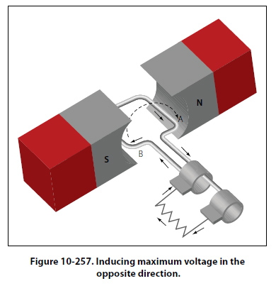
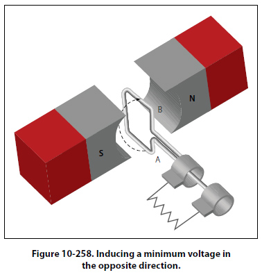
decreases because both sides of the loop (A and B) are approximately parallel to the lines of force and the rate of cutting is reduced. When the loop is vertical, no lines of force are cut since the wires are momentarily traveling parallel to the magnetic lines of force, and there is no induced voltage. As the rotation of the loop continues, the number of lines of force cut increases until the loop has rotated an additional 90° to a horizontal plane. As shown in Figure 10-257, the number of lines of force cut and the induced voltage once again are maximum.
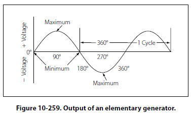
If the voltage induced throughout the entire 360° of rotation is plotted, the curve shown in Figure 10-259 results. This voltage is called an alternating voltage because of its reversal from positive to negative value — first in one direction and then in the other.
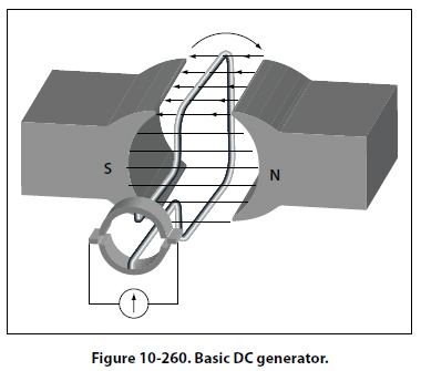
To use the voltage generated in the loop for producing a current flow in an external circuit, some means must be provided to connect the loop of wire in series with the external circuit. Such an electrical connection can be effected by opening the loop of wire and connecting its two ends to two metal rings, called slip rings, against which two metal or carbon brushes ride. The brushes are connected to the external circuit. By replacing the slip rings of the basic AC generator with two half cylinders, called a commutator, a basic DC generator is obtained.
[Figure 10-260] In this illustration, the black side of the coil is connected to the black segment, and the white side of the coil to the white segment. The segments are insulated from each other. The two stationary brushes are placed on opposite sides of the commutator and are so mounted that each brush contacts each segment of the commutator as the latter revolves simultaneously with the loop. The rotating parts of a DC generator (coil and commutator) are called an armature. The generation of an emf by the loop rotating in the magnetic field is the same for both AC and DC generators, but the action of the commutator produces a DC voltage. |
| ©AvStop Online Magazine Contact Us Return To Books |