![]()
|
|
||
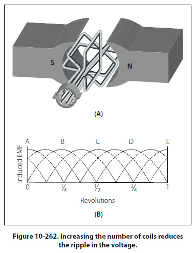
Position D At position D, commutator action reverses the current in the external circuit, and the second half cycle has the same waveform as the first half cycle. The process of commutation is sometimes called rectification, since rectification is the converting of an AC voltage to a DC voltage. The Neutral Plane At the instant that each brush is contacting two segments on the commutator (positions A, C, and E in Figure 10-261), a direct short circuit is produced. If an emf were generated in the loop at this time, a high current would flow in the circuit, causing an arc and thus damaging the commutator. For this reason, the brushes must be placed in the exact position where the short will occur when the generated emf is zero. This position is called the neutral plane. If the brushes are installed properly, no sparking will occur between the brushes and the commutator. Sparking is an indication of improper brush placement, which is the main cause of improper commutation. The voltage generated by the basic DC generator in Figure 10-261 varies from zero to its maximum value twice for each revolution of the loop. This variation of DC voltage is called “ripple," and may be reduced by using more loops, or coils, as shown in A of Figure 10-262. As the number of loops is increased, the variation between maximum and minimum values of voltage is reduced (view B of Figure 10-262), and the output voltage of the generator approaches a steady DC value. In view A of Figure 10-262 the number of commutator segments is increased in direct proportion to the number of loops; that is, there are two segments for one loop, four segments for two loops, and eight segments for four loops.
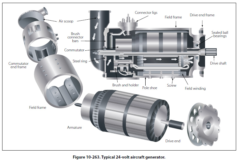
The voltage induced in a single turn loop is small. Increasing the number of loops does not increase the maximum value of generated voltage, but increasing the number of turns in each loop will increase this value. Within narrow limits, the output voltage of a DC generator is determined by the product of the number of turns per loop, the total flux per pair of poles in the machine, and the speed of rotation of the armature. An AC generator, or alternator, and a DC generator are identical as far as the method of generating voltage in the rotating loop is concerned. However, if the current is taken from the loop by slip rings, it is an alternating current, and the generator is called an AC generator, or alternator. If the current is collected by a commutator, it is direct current, and the generator is called a DC generator. Construction Features of DC Generators Generators used on aircraft may differ somewhat in design, since various manufacturers make them. All, however, are of the same general construction and operate similarly. The major parts, or assemblies, of a DC generator are a field frame (or yoke), a rotating armature, and a brush assembly. The parts of a typical aircraft generator are shown in Figure 10-263.
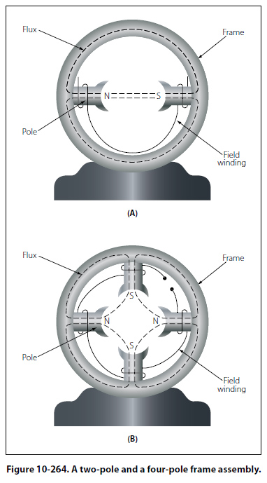
Field Frame The field frame is also called the yoke, which is the foundation or frame for the generator. The frame has two functions: It completes the magnetic circuit between the poles and acts as a mechanical support for the other parts of the generator. In View A of Figure 10-264, the frame for a two-pole generator is shown in a cross-sectional view. A four-pole generator frame is shown in View B of Figure 10-264.
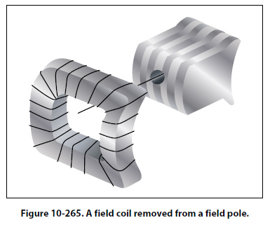
In small generators, the frame is made of one piece of iron, but in larger generators, it is usually made up of two parts bolted together. The frame has high magnetic properties and, together with the pole pieces, forms the major part of the magnetic circuit. The field poles, shown in Figure 10-264, are bolted to the inside of the frame and form a core on which the field coil windings are mounted. The poles are usually laminated to reduce eddy current losses and serve the same purpose as the iron core of an electromagnet; that is, they concentrate the lines of force produced by the field coils. The entire frame including field poles, is made from high quality magnetic iron or sheet steel. A practical DC generator uses electromagnets instead of permanent magnets. To produce a magnetic field of the necessary strength with permanent magnets would greatly increase the physical size of the generator. The field coils are made up of many turns of insulated wire and are usually wound on a form that fits over the iron core of the pole to which it is securely fastened. [Figure 10-265] The exciting current, which is used to produce the magnetic field and which flows through the field coils, is obtained from an external source or from the generated DC of the machine. No electrical
connection exists between the windings of the field coils and the pole pieces. Most field coils are connected so that the poles show alternate polarity. Since there is always one north pole for each south pole, there must always be an even number of poles in any generator. Note that the pole pieces in Figure 10-264 project from the frame. Because air offers a great amount of reluctance to the magnetic field, this design reduces the length of the air gap between the poles and the rotating armature and increases the efficiency of the generator. When the pole pieces are made to project as shown in Figure 10-264, they are called salient poles. |
| ©AvStop Online Magazine Contact Us Return To Books |