![]()
|
|
||
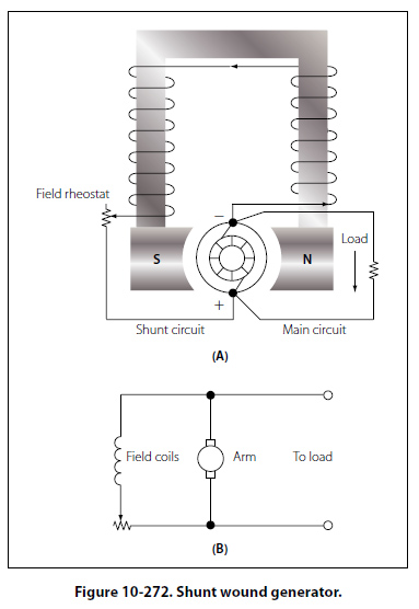
Shunt Wound DC Generators A generator having a field winding connected in parallel with the external circuit is called a shunt generator, as shown in views A and B of Figure 10-272. The field coils of a shunt generator contain many turns of small wire; the magnetic strength is derived from the large number of turns rather than the current strength through the coils. If a constant voltage is desired, the shunt wound generator is not suitable for rapidly fluctuating loads. Any increase in load causes a decrease in the terminal or output voltage, and any decrease in load causes an increase in terminal voltage; since the armature and the load are connected in series, all current flowing in the external circuit passes through the armature winding. Because of the resistance in the armature winding, there is a voltage drop (IR drop = current × resistance). As the load increases, the armature current increases and the IR drop in the armature increases. The voltage delivered to the terminals is the difference between the induced voltage and the voltage drop; therefore, there is a decrease in terminal voltage. This decrease in voltage causes a decrease in field strength, because the current in the field coils decreases in proportion to the decrease in terminal voltage; with a weaker field, the voltage is further decreased. When the load decreases, the output voltage increases accordingly, and a larger current flows in the windings. This action is cumulative, so the output voltage continues to rise to a point called field saturation, after which there is no further increase in output voltage.
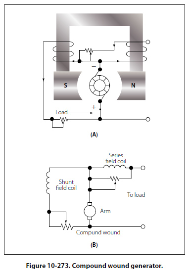
The terminal voltage of a shunt generator can be controlled by means of a rheostat inserted in series with the field windings as shown in Figure 10-272A. As the resistance is increased, the field current is reduced; consequently, the generated voltage is reduced also. For a given setting of the field rheostat, the terminal voltage at the armature brushes will be approximately equal to the generated voltage minus the IR drop produced by the load current in the armature; thus, the voltage at the terminals of the generator will drop as the load is applied. Certain voltage sensitive devices are available which automatically adjust the field rheostat to compensate for variations in load. When these devices are used, the terminal voltage remains essentially constant. Compound Wound DC Generators A compound wound generator combines a series winding and a shunt winding in such a way that the characteristics of each are used to advantage. The series field coils are made of a relatively small number of turns of large copper conductor, either circular or rectangular in cross section, and are connected in series with the armature circuit. These coils are mounted on the same poles on which the shunt field coils are mounted and, therefore, contribute a magnetomotive force which influences the main field flux of the generator. A diagrammatic and a schematic illustration of a compound wound generator is shown in A and B of Figure 10-273.
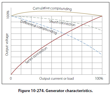
If the ampere turns of the series field act in the same direction as those of the shunt field, the combined magnetomotive force is equal to the sum of the series and shunt field components. Load is added to a compound generator in the same manner in which load is added to a shunt generator, by increasing the number of parallel paths across the generator terminals. Thus, the decrease in total load resistance with added load is accompanied by an increase in armature circuit and series field circuit current. The effect of the additive series field is that of increased field flux with increased load. The extent of the increased field flux depends on the degree of saturation of the field as determined by the shunt field current. Thus, the terminal voltage of the generator may increase or decrease with load, depending on the influence of the series field coils. This influence is referred to as the degree of compounding. A flat compound generator is one in which the no load and full load voltages have the same value; whereas an under compound generator has a full load voltage less than the no load value, and an over compound generator has a full load voltage which is higher than the no load value. Changes in terminal voltage with increasing load depend upon the degree of compounding. If the series field aids the shunt field, the generator is said to be cumulative compounded. If the series field opposes the shunt field, the machine is said to be differentially compounded, or is called a differential generator. Compound generators are usually designed to be overcompounded. This feature permits varied degrees of compounding by connecting a variable shunt across the series field. Such a shunt is sometimes called a diverter. Compound generators are used where voltage regulation is of prime importance. Differential generators have somewhat the same characteristics as series generators in that they are essentially constant current generators. However, they generate rated voltage at no load, the voltage dropping materially as the load current increases. Constant current generators are ideally suited as power sources for electric arc welders and are used almost universally in electric arc welding. If the shunt field of a compound generator is connected across both the armature and the series field, it is known as a long shunt connection, but if the shunt field is connected across the armature alone, it is called a short shunt connection. These connections produce essentially the same generator characteristics. A summary of the characteristics of the various types of generators discussed is shown graphically in Figure 10-274.
|
| ©AvStop Online Magazine Contact Us Return To Books |