![]()
|
|
||
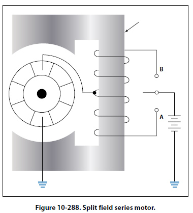
Counter Electromotive Force (emf) The armature resistance of a small, 28-volt DC motor is extremely low, about 0.1 ohm. When the armature is connected across the 28-volt source, current through the armature will apparently be I = E/R = 28/0.1 = 280 amperes This high valve of current flow is not only impracticable but also unreasonable, especially when the current drain, during normal operation of a motor, is found to be about 4 amperes. This is because the current through a motor armature during operation is determined by more factors than ohmic resistance. When the armature in a motor rotates in a magnetic field, a voltage is induced in its windings. This voltage is called the back or counter emf (electromotive force) and is opposite in direction to the voltage applied to the motor from the external source. Counter emf opposes the current, which causes the armature to rotate. The current flowing through the armature, therefore, decreases as the counter emf increases. The faster the armature rotates, the greater the counter emf. For this reason, a motor connected to a battery may draw a fairly high current on starting, but as the armature speed increases, the current flowing through the armature decreases. At rated speed, the counter emf may be only a few volts less than the battery voltage. Then, if the load on the motor is increased, the motor will slow down, less counter emf will be generated, and the current drawn from the external source will increase. In a shunt motor, the counter emf affects only the current in the armature, since the field is connected in parallel across the power source. As the motor slows down and the counter emf decreases, more current flows through the armature, but the magnetism in the field is unchanged. When the series motor slows down, the counter emf decreases and more current flows through the field and the armature, thereby strengthening their magnetic fields. Because of these characteristics, it is more difficult to stall a series motor than a shunt motor. Types of Duty Electric motors are called upon to operate under various conditions. Some motors are used for intermittent operation; others operate continuously. Motors built for intermittent duty can be operated for short periods only and, then, must be allowed to cool before being operated again. If such a motor is operated for long periods under full load, the motor will be overheated. Motors built for continuous duty may be operated at rated power for long periods. Reversing Motor Direction By reversing the direction of current flow in either the armature or the field windings, the direction of a motor’s rotation may be reversed. This will reverse the magnetism of either the armature or the magnetic field in which the armature rotates. If the wires connecting the motor to an external source are interchanged, the direction of rotation will not be reversed, since changing these wires reverses the magnetism of both field and armature and leaves the torque in the same direction as before. One method for reversing direction of rotation employs two field windings wound in opposite directions on the same pole. This type of motor is called a split field motor. Figure 10-288 shows a series motor with a split field winding.
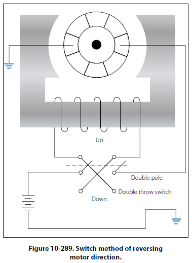
The single pole, double throw switch makes it possible to direct current through either of the two windings. When the switch is placed in the lower position, current flows through the lower field winding, creating a north pole at the lower field winding and at the lower pole piece, and a south pole at the upper pole piece. When the switch is placed in the upper position, current flows through the upper field winding, the magnetism of the field is reversed, and the armature rotates in the opposite direction. Some split field motors are built with two separate field windings wound on alternate poles. The armature in such a motor, a four pole reversible motor, rotates in one direction when current flows through the windings of one set of opposite pole pieces, and in the opposite direction when current flows through the other set of windings. Another method of direction reversal, called the switch method, employs a double pole, double throw switch which changes the direction of current flow in either the armature or the field. In the illustration of the switch method shown in Figure 10-289, current direction may be reversed through the field but not through the armature.
When the switch is thrown to the “up" position, current flows through the field winding to establish a north pole at the right side of the motor and a south pole at the left side of the motor. When the switch is thrown to the “down" position, this polarity is reversed and the armature rotates in the opposite direction. |
| ©AvStop Online Magazine Contact Us Return To Books |