![]()
|
|
||
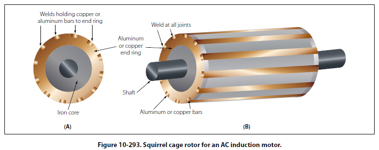
Construction of Induction Motor The stationary portion of an induction motor is called a stator, and the rotating member is called a rotor. Instead of salient poles in the stator, as shown in A of Figure 10-292, distributed windings are used; these windings are placed in slots around the periphery of the stator. It is usually impossible to determine the number of poles in an induction motor by visual inspection, but the information can be obtained from the nameplate of the motor. The nameplate usually gives the number of poles and the speed at which the motor is designed to run. This rated, or nonsynchronous, speed is slightly less than the synchronous speed. To determine the number of poles per phase on the motor, divide 120 times the frequency by the rated speed. Written as an equation, it is: P = 120 × f/N Where: P is the number of poles per phase, The result will be very nearly equal to the number of poles per phase. For example, consider a 60 cycle, three phase motor with a rated speed of 1,750 rpm. In this case: P = 120 × 60/1,750 = 7,200/1,750=4.1 Therefore, the motor has four poles per phase. If the number of poles per phase is given on the nameplate, the synchronous speed can be determined by dividing 120 times the frequency by the number of poles per phase. In the example used above, the synchronous speed is equal to 7,200 divided by 4, or 1,800 rpm. The rotor of an induction motor consists of an iron core having longitudinal slots around its circumference in which heavy copper or aluminum bars are embedded. These bars are welded to a heavy ring of high conductivity on either end. The composite structure is sometimes called a squirrel cage, and motors containing such a rotor are called squirrel cage induction motors. [Figure 10-293]
Induction Motor Slip When the rotor of an induction motor is subjected to the revolving magnetic field produced by the stator windings, a voltage is induced in the longitudinal bars. The induced voltage causes a current to flow through the bars. This current, in turn, produces its own magnetic field, which combines with the revolving field so that the rotor assumes a position in which the induced voltage is minimized. As a result, the rotor revolves at very nearly the synchronous speed of the stator field, the difference in speed being just sufficient enough to induce the proper amount of current in the rotor to overcome the mechanical and electrical losses in the rotor. If the rotor were to turn at the same speed as the rotating field, the rotor conductors would not be cut by any magnetic lines of force, no emf would be induced in them, no current could flow, and there would be no torque. The rotor would then slow down. For this reason, there must always be a difference in speed between the rotor and the rotating field. This difference in speed is called slip and is expressed as a percentage of the synchronous speed. For example, if the rotor turns at 1,750 rpm and the synchronous speed is 1,800 rpm, the difference in speed is 50 rpm. The slip is then equal to 50/1,800 or 2.78 percent. |
| ©AvStop Online Magazine Contact Us Return To Books |