![]()
|
|
||
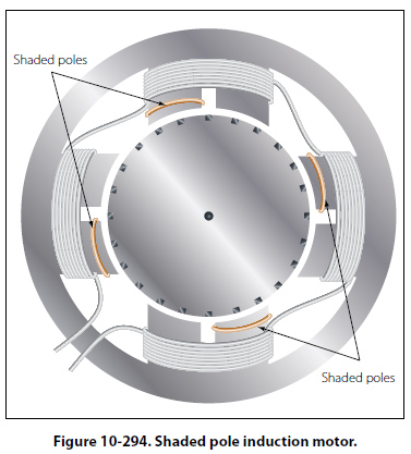
Single Phase Induction Motor The previous discussion has applied only to polyphase motors. A single-phase motor has only one stator winding. This winding generates a field, which merely pulsates, instead of rotating. When the rotor is stationary, the expanding and collapsing stator field induces currents in the rotor. These currents generate a rotor field opposite in polarity to that of the stator. The opposition of the field exerts a turning force on the upper and lower parts of the rotor trying to turn it 180° from its position. Since these forces are exerted through the center of the rotor, the turning force is equal in each direction. As a result, the rotor does not turn. If the rotor has started turning, it will continue to rotate in the direction in which it is started, since the turning force in that direction is aided by the momentum of the rotor. Shaded Pole Induction Motor The first effort in the development of a self-starting, single-phase motor was the shaded pole induction motor. [Figure 10-294] This motor has salient poles, a portion of each pole being encircled by a heavy copper ring. The presence of the ring causes the magnetic field through the ringed portion of the pole face to lag appreciably behind that through the other part of the pole face. The net effect is the production of a slight component of rotation of the field, sufficient to cause the rotor to revolve. As the rotor accelerates, the torque increases until the rated speed is obtained. Such
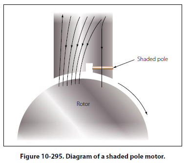
motors have low starting torque and find their greatest application in small fan motors where the initial torque required is low. In Figure 10-295, a diagram of a pole and the rotor is shown. The poles of the shaded pole motor resemble those of a DC motor.
A low resistance, short-circuited coil or copper band is placed across one tip of each small pole, from which, the motor gets the name of shaded pole. The rotor of this motor is the squirrel cage type. As the current increases in the stator winding, the flux increases. A portion of this flux cuts the low resistance shading coil. This induces a current in the shading coil, and by Lenz’s law, the current sets up a flux that opposes the flux inducing the current. Hence, most of the flux passes through the unshaded portion of the poles, as shown in Figure 10-295. When the current in the winding and the main flux reaches a maximum, the rate of change is zero; thus, no emf is induced in the shading coil. A little later, the shading coil current, which causes the induced emf to lag, reaches zero, and there is no opposing flux. Therefore, the main field flux passes through the shaded portion of the field pole. The main field flux, which is now decreasing, induces a current in the shading coil. This current sets up a flux that opposes the decrease of the main field flux in the shaded portion of the pole. The effect is to concentrate the lines of force in the shaded portion of the pole face. In effect, the shading coil retards, in time phase, the portion of the flux passing through the shaded part of the pole. This lag in time phase of the flux in the shaded tip causes the flux to produce the effect of sweeping across the face of the pole, from left to right in the direction of the shaded tip. This behaves like a very weak rotating magnetic field, and sufficient torque is produced to start a small motor. The starting torque of the shaded pole motor is exceedingly weak, and the power factor is low. Consequently, it is built in sizes suitable for driving such devices as small fans. |
| ©AvStop Online Magazine Contact Us Return To Books |